6-2
SUPERSERVER 7047R-TRF USER'S MANUAL
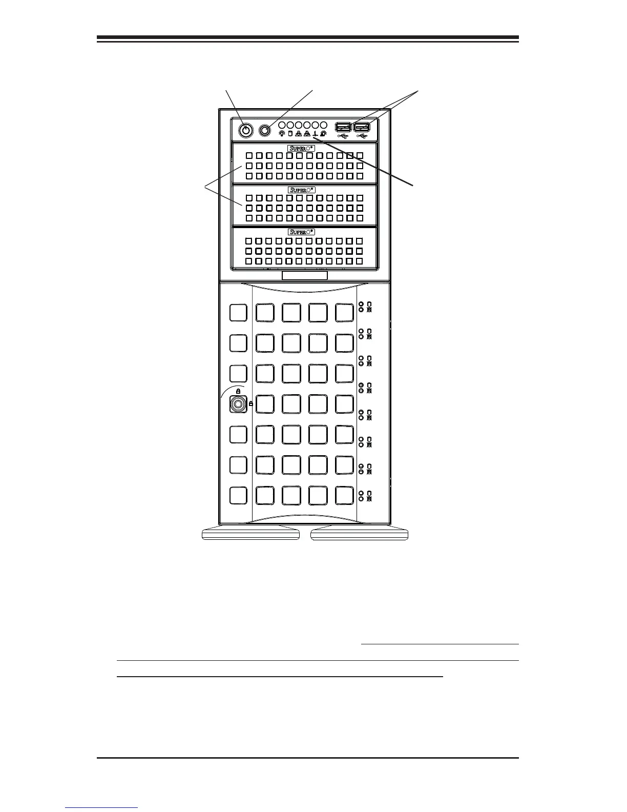
Figure 6-1. Chassis Front View
6-2 Front Control Panel
The front control panel must be connected to the JF1 connector on the serverboard
to provide you with system status and alarm indications. A ribbon cable has bundled
these wires together to simplify this connection. Connect the cable from JF1 on
the serverboard (making sure the red wire plugs into pin 1) to the appropriate
comnnector on the front control panel PCB (printed circuit board). Pull all excess
cabling over to the control panel side of the chassis. The LEDs on the control
panel inform you of system status -See Chapter 3 for details. See Chapter 5 for
details on JF1.
System LEDs
System ResetMain Power
5.25" Drive Bays
USB Ports
8 Drive Bays
(behind locking bezel)
 Loading...