5-20
SUPERSERVER 7047R-TRF USER'S MANUAL
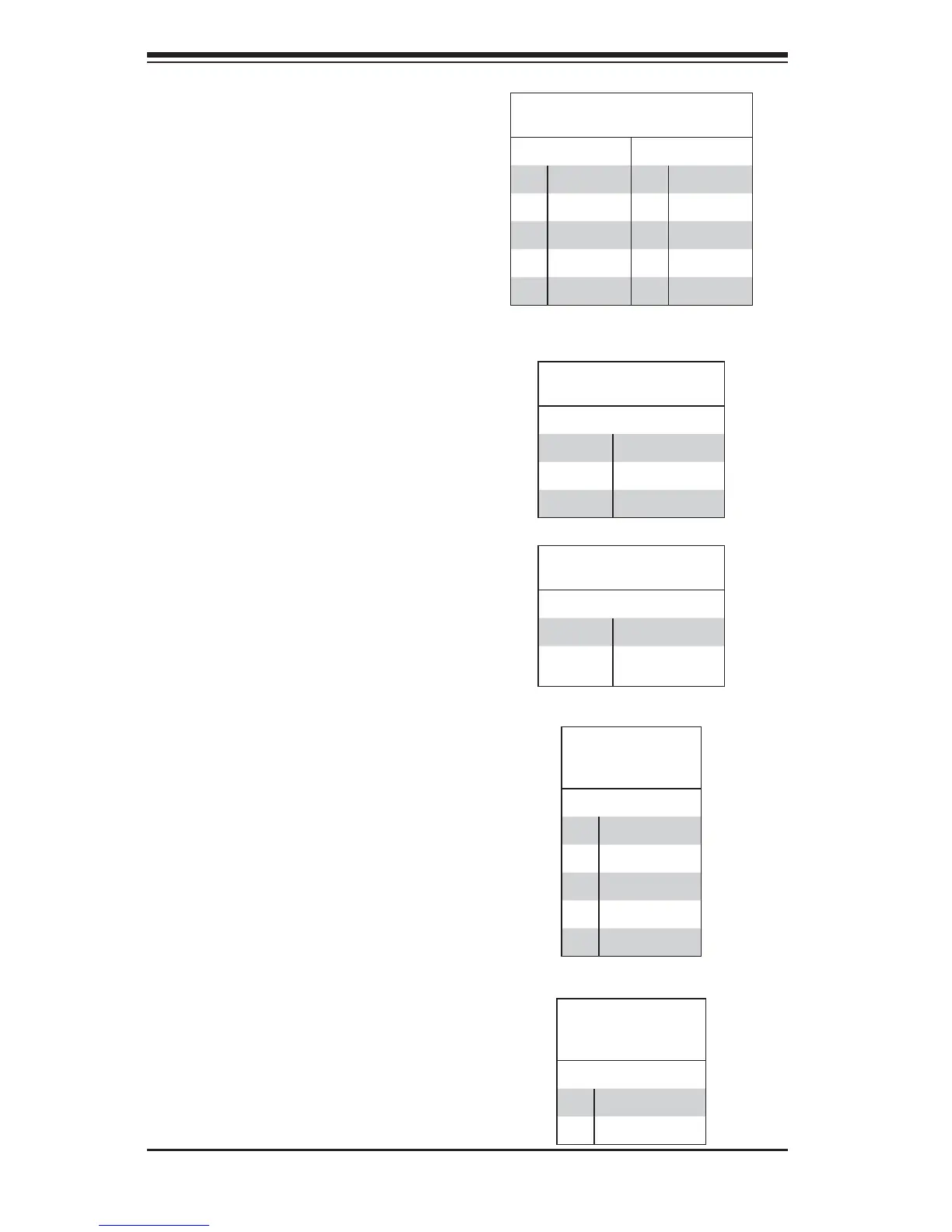
PWR LED Connector
Pin Defi nitions (JD1)
Pin Setting Defi nition
Pin 1 Anode (+)
Pin2 Cathode (-)
Pin3 NA
Speaker Connector
Pin Defi nitions
Pin Setting Defi nition
Pins 4~7 External Speaker
Pins 6~7 Internal Speaker
(Default)
Power LED/Speaker
On JD1 header, pins 1-3 are used for
power LED indication, and pins 4-7 are
for the speaker. See the tables on the
right for pin defi nitions. Please note
that the speaker connector pins (4-7)
are used with an external speaker. If
you wish to use the onboard speaker,
you should close pins 6-7 with a
jumper (Default).
Serial Port Pin Defi nitions
(COM1/COM2)
Pin # Defi nition Pin # Defi nition
1 DCD 6 DSR
2 RXD 7 RTS
3 TXD 8 CTS
4 DTR 9 RI
5 Ground 10 NC
(NC = No connection)
Serial Ports
Two COM connections (COM1/COM2)
are located on the motherboard.
COM1 is located on the Backplane
I/O panel. COM2, located close to
PCI-E Slot1, provides front access
support. See the table on the right for
pin defi nitions.
Power SMB (I
2
C) Connector
Power System Management Bus (I2C)
Connector (JI2C1) monitors power
supply, fan and system temperatures.
See the table on the right for pin
defi nitions.
PWR SMB
Pin Defi nitions
(JI2C1)
Pin# Defi nition
1 Clock
2 Data
3 PWR Fail
4 Ground
5 +3.3V
Chassis Intrusion
A Chassis Intrusion header is located
at JL1 on the motherboard. Attach an
appropriate cable from the chassis to
inform you of a chassis intrusion when
the chassis is opened.
Chassis Intrusion
Pin Defi nitions
(JL1)
Pin# Defi nition
1 Intrusion Input
2 Ground
 Loading...