5-22
SUPERSERVER 7047R-TRF USER'S MANUAL
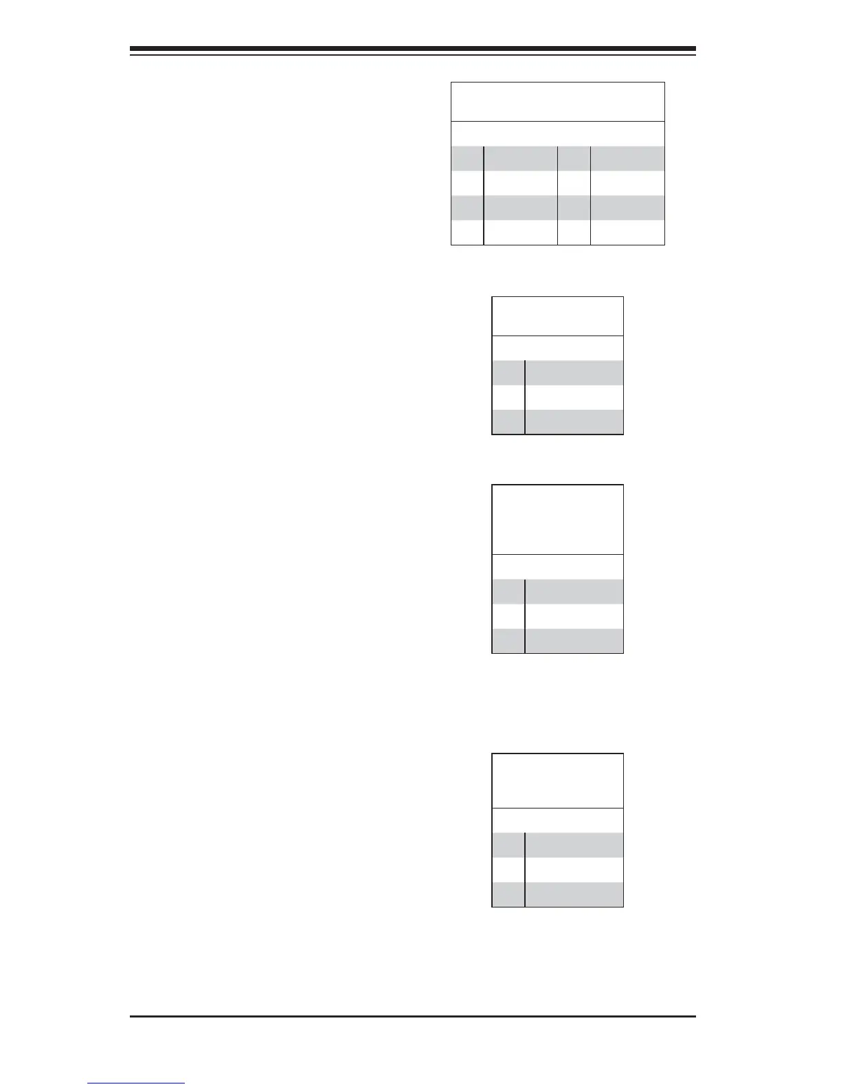
T-SGPIO 1/2 Headers
Two SGPIO (Serial-Link General
Purpose Input/Output) headers are
located on the motherboard. These
headers support Serial_Link interface
for onboard SATA connections. See
the table on the right for pin defi nitions.
SGPIO Header Pin Defi nitions
(T-SGPIO1/T-SGPIO2)
Pin# Defi nition Pin# Defi nition
1 NC 2 Data In
3 Ground 4 Data Out
5 Load 6 Ground
7 Clock 8 NC
(NC = No Connection)
ME Recovery
Pin Defi nitions
Pin# Defi nition
1 No Connection
2 Signal
3 Ground
BIOS Recovery
JP3 (BIOS Recovery) is used to
enhance system performance and
power effi ciency. In the single operation
mode, online upgrade will be available
via Recovery mode. See the table on
the right for pin defi nitions.
Legacy Wake-On-LAN Header
(JSTBY)
The onboard LAN por ts do not need
a WOL header to support their Wake-
On-LAN function. Instead, the legacy
WOL header was preserved (JSTBY)
to provide convenience for some
embedded customers who need an
internal power source from the board.
See the table on the right for pin
defi nitions.
Legacy Wake-
On-LAN Header
Pin Defi nitions
(JSTBY)
Pin# Defi nition
1 +5V Standby
2 Ground
3 Wake-up (signal)
DOM Power Connector
A power connector for SATA DOM
(Disk_On_Module) devices is located
at JWF1. Connect an appropriate
cable here to provide power support
for your DOM devices.
DOM Power
Connector
Pin Defi nitions
Pin# Defi nition
1 +5V
2 Ground
3 Ground
Video Connection
A Video (VGA) port is located next to
LAN2 on the I/O backplane. Refer to
the board layout below for the location.
 Loading...