1-6
X9SCM/X9SCM-F/X9SCL/X9SCL-F User’s Manual
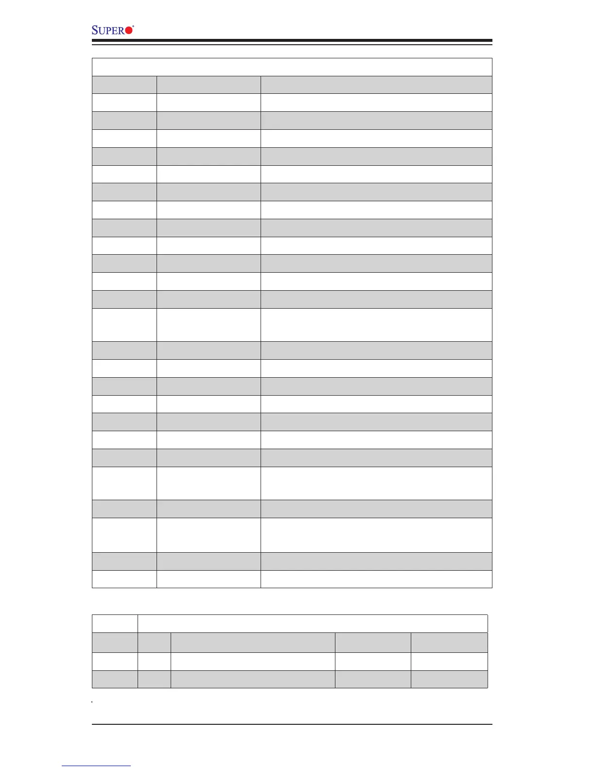
X9SCM/X9SCM-F/X9SCL/X9SCL-F LED Indicators
Number LED Description Color/State Status
14 LE7 IPMI Heartbeat LED Green: Blinking IPMI Active
28 LE2 Onboard Standby PWR LED Green: Solid on Power On
X9SCM/X9SCM-F/X9SCL/X9SCL-F Headers/Connectors
Number Connector Description
21 B1 Onboard Battery
4,16 COM1/COM2 COM1/2 Serial Connection Headers
35 BIOS SPI BIOS
42,38,37,7,30 Fans 1~4, Fan A System/CPU Fan Headers
36 J31 SPI Programming (internal use)
43 JF1 Front Panel Control Header
33 JL1 Chassis Intrusion Header
44 JLED1 Power LED Indicator Header
46 JPW1 24-pin ATX Main Power Connector (Required)
47 JPW2 +12V 8-pin CPU power Connector (Required)
1 KB/Mouse Keyboard/Mouse Connectors
8,9,3 LAN1/LAN2, IPMI_LAN Gigabit (RJ45) Ports (LAN1/2), IPMI_LAN (F-models)
50,49 I-SATA 0/1 Serial ATA Ports 0/1 (X9SCL: SATA-II Ports, X9SCM:
SATA-III Ports)
27,26,25,24 I-SATA 0~5 SATA-II Ports
45 JPI
2
C PWR supply (I
2
C) System Management Bus
40 JSPK Speaker Header (Pins 3/4: Internal, 1~4:External)
5 JTPM Trusted Platform Module (TPM) Header
29 JWF1 SATA DOM (Device_On_Module) Power Connector
15 JWOL Wake_On_LAN Header
39 SPKR1 Internal Speaker/Buzzer
31, 32 T-SGPIO-1/2 Serial_Link General Purpose IO 1/2 Headers (5V Gen1/
Gen 2)
2 USB0/1 Backpanel USB 0/1
20,19,18 USB2/3, USB4/5,
USB 12/13
Front Accessible USB Connections (via 3 Headers)
23 USB 11 Front Accessible Type A USB Connector
6 VGA Onboard Video Port