Chapter 2: Installation
2-17
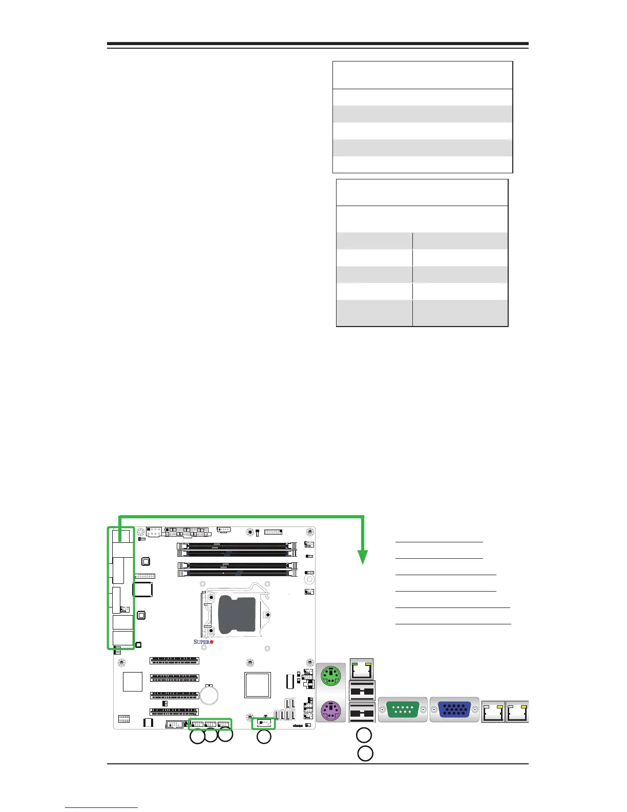
1. Backpanel USB 0
2. Backpanel USB 1
3. Front Panel USB 2/3
4. Front Panel USB 4/5
5. Front Panel USB 12/13
6. Internal 'Type A' USB 11
Universal Serial Bus (USB)
Two Universal Serial Bus ports (USB
0/1) are located on the I/O back panel.
In addition, six USB connections (USB
2/3, USB 4/5, USB 12/13) are used to
provide front chassis access. USB 11
is a Type A Connector. (USB Cables
are not included). See the tables on
the right for pin denitions.
Back Panel USB 0/1
PinDenitions
Pin# Denition Pin# Denition
1 +5V 5 +5V
2 USB_PN0 6 USB_PN1
3 USB_PP0 7 USB_PP1
4 Ground 8 Ground
Front Panel USB 2/3, 4/5, 12/13
PinDenitions
USB 2/4/12/11
Pin # Denition
USB 3/5/13
Pin # Denition
1 +5V 6 +5V
2 USB_PN2 7 USB_PN3
3 USB_PP2 8 USB_PP3
4 Ground 9 Ground
5 No Con-
nection
10 Key