J31
JTPM
J29
JL1
JI2C2
JI2C1
T-SGPIO1
JWF1
JPW2
JWOL
JSPK
JPI2C
JPW1
COM1
SPKR1
JBT1
LE2
JWD
JLED1
JPL2
JPG1
JPB
JPL1
JPUSB1
F A N 1
F A N A
F A N 3
F A N 2
DDR3 1066/1333 UDIMM required
USB4/5
USB 12/13
_LAN
IPMI
COM2
VGA
USB11
DIMM2B
DIMM2A
USB2/3
Slot6 PCI-E 2.0 x8
JF1
I-SATA2
Slot4 PCI-E 2.0 x4 on x8
KB/MOUSE
DIMM1B
DIMM1A
CPU
Slot7 PCI-E 2.0 x8
BIOS
B1
Battery
PHY
BMC
CTRL
82574L
S I/O
T-SGPIO2
FP CTRL
Cougar Point
Standard PCH
Memory Chip
X9SCM/X9SCL(-F) Rev.1.0
Fan4
PHY
82579
PHY
(For X9SCM only)
(*I-SATA 0/1:
X9SCL: SATA2, X9SCM: SATA3)
Socket H2
LGA 1155
CPU
I-SATA4
I-SATA5
I-SATA3
I-SATA1
I-SATA0
Slot5 PCI-E 2.0 x4 on x8
USB/0/1
LAN1
LAN2
LE7
JPME1
JPME2
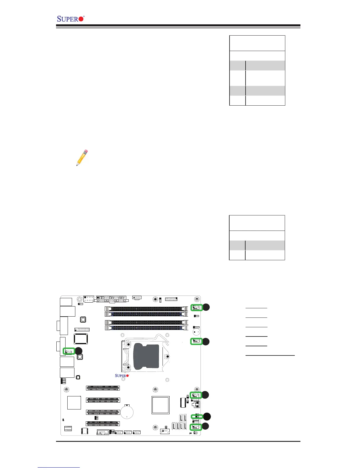
Fan Header
PinDenitions
Pin# Denition
1 Ground (Black)
2 2.5A/+12V
(Red)
3 Tachometer
4 PWM_Control
Fan Headers
The X9SCM/X9SCM-F/X9SCL/X9SCL-F has
ve fan headers (Fan 1~Fan 4 and Fan A).
These fans are 4-pin fan headers. However,
Pins 1-3 of the fan headers are backward
compatible with the traditional 3-pin fans. A fan
speed control setting in the BIOS Hardware
Monitoring section allows the BIOS to auto-
matically set fan speeds based on the system
temperature. Refer to the table on the right for
pin denitions.
Note: Please use all 3-pin fans or all
4-pin fans on a motherboard. Please
do not use 3-pin fans and 4-pin fans
on the same board.
A
B
A. Fan 1
B. Fan 2
C. Fan 3
D. Fan 4
E. Fan A
F. Chassis Intrusion
C
D
E
Chassis Intrusion
A Chassis Intrusion header is located at JL1 on
the motherboard. Attach the appropriate cable
from the chassis to inform you of a chassis intru-
sion when the chassis is opened.
Chassis Intrusion
PinDenitions(JL1)
Pin# Denition
1 Intrusion Input
2 Ground