J31
JTPM
J29
JL1
JI2C2
JI2C1
T-SGPIO1
JWF1
JPW2
JWOL
JSPK
JPI2C
JPW1
COM1
SPKR1
JBT1
LE2
JWD
JLED1
JPL2
JPG1
JPB
JPL1
JPUSB1
F A N 1
F A N A
F A N 3
F A N 2
DDR3 1066/1333 UDIMM required
USB4/5
USB 12/13
_LAN
IPMI
COM2
VGA
USB11
DIMM2B
DIMM2A
USB2/3
Slot6 PCI-E 2.0 x8
JF1
I-SATA2
Slot4 PCI-E 2.0 x4 on x8
KB/MOUSE
DIMM1B
DIMM1A
CPU
Slot7 PCI-E 2.0 x8
BIOS
B1
Battery
PHY
BMC
CTRL
82574L
S I/O
T-SGPIO2
FP CTRL
Cougar Point
Standard PCH
Memory Chip
X9SCM/X9SCL(-F) Rev.1.0
Fan4
PHY
82579
PHY
(For X9SCM only)
(*I-SATA 0/1:
X9SCL: SATA2, X9SCM: SATA3)
Socket H2
LGA 1155
CPU
I-SATA4
I-SATA5
I-SATA3
I-SATA1
I-SATA0
Slot5 PCI-E 2.0 x4 on x8
USB/0/1
LAN1
LAN2
LE7
JPME1
JPME2
B
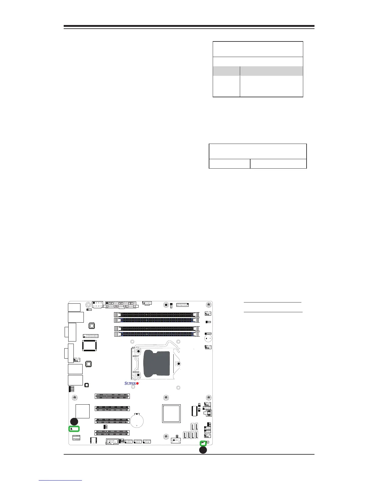
Onboard PWR LED Indicator
LED Status
Status Denition
Off System Off
On System on, or
System off and PWR
Cable Connected
Onboard Power LED
An Onboard Power LED is located
at LE2 on the motherboard. When
LE2 is on, the AC power cable is
connected. Make sure to disconnect
the power cable before removing or
installing any component. See the
layout below for the LED location.
A. Onboard PWR LED
B. IPMI Heartbeat LED
IPMI Heartbeat LED
An IPMI Heartbeat LED is located at
LE7. When LE7 blinks, the IPMI functions
properly. Refer to the table on the right
for details. Also see the layout below for
the LED location.
IPMI Heartbeat LED Indicator (LE7)
LED Settings
Green: Blinking IPMI is Active
A