2-28
X9SCM/X9SCM-F/X9SCL/X9SCL-F User's Manual
A
B
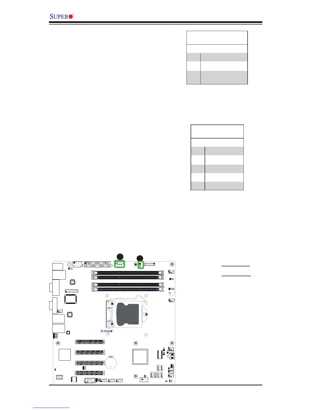
A. PWR LED
B. PWR SMB
Power Supply I
2
C Connector
Power Supply I
2
C Connector, located
at JPI
2
C, monitors the status of the
power supply, fan and system tem-
perature. See the table on the right
for pin denitions.
PWR Supply I
2
C
PinDenitions
Pin# Denition
1 Clock
2 Data
3 PWR Fail
4 Ground
5 3.3V
Onboard Power LED
An onboard Power LED header is
located at JLED1. This Power LED
header is connected to Front Control
Panel located at JF1 to indicate the
status of system power. See the table
on the right for pin denitions.
Onboard PWR LED
PinDenitions
Pin# Denition
1 VCC
2 No Connection
3 Connection to PWR
LED in JF1
J31
JTPM
J29
JL1
JI2C2
JI2C1
T-SGPIO1
JWF1
JPW2
JWOL
JSPK
JPI2C
JPW1
COM1
SPKR1
JBT1
LE2
JWD
JLED1
JPL2
JPG1
JPB
JPL1
JPUSB1
F A N 1
F A N A
F A N 3
F A N 2
DDR3 1066/1333 UDIMM required
USB4/5
USB 12/13
_LAN
IPMI
COM2
VGA
USB11
DIMM2B
DIMM2A
USB2/3
Slot6 PCI-E 2.0 x8
JF1
I-SATA2
Slot4 PCI-E 2.0 x4 on x8
KB/MOUSE
DIMM1B
DIMM1A
CPU
Slot7 PCI-E 2.0 x8
BIOS
B1
Battery
PHY
BMC
CTRL
82574L
S I/O
T-SGPIO2
FP CTRL
Cougar Point
Standard PCH
Memory Chip
X9SCM/X9SCL(-F) Rev.1.0
Fan4
PHY
82579
PHY
(For X9SCM only)
(*I-SATA 0/1:
X9SCL: SATA2, X9SCM: SATA3)
Socket H2
LGA 1155
CPU
I-SATA4
I-SATA5
I-SATA3
I-SATA1
I-SATA0
Slot5 PCI-E 2.0 x4 on x8
USB/0/1
LAN1
LAN2
LE7
JPME1
JPME2