INST
MIX
SPLIT
STEREO
MIC/LINE
ON
OFF
-20dB
LINE
MIC
LEFT
RIGHT
MIC/LINE
OPEN/CLOSE
SPEAKER
ALC/ATT
INPUT
ON
OFF
DIGITAL
ANALOG
PHONE SELECTOR
MIC/LINE
LINE
CD
PHONE/SPEAKER
MIC/LINE
AUX
R
LINE OUT
MIC
INT MIC
LEVEL
L
PHONES
LINE OUT
CD PLAY/RECORD
PUSH
NEUTRIK
PUSHPUSH
NEUTRIK
Powering Up
1. Check that the AC power cord fits snuggly into the
power cord jack on the back panel.
2. Make sure the back panel MASTER POWER switch is
ON. The STANDBY light should now be ON. Slide
the STANDBY POWER switch to the right. Upon
power up, this light will dim and the display will
come on.
TIP:TIP:
TIP:TIP:
TIP: If you are switching power ON/OFF via the
Remote or if you wish to retain certain settings in
memory when powering off, leave the back panel
MASTER POWER switch ON.
Setting Up Instruments, Mics
and other Sound Sources
The PSD340 is designed to work with microphones,
instruments, and line level sources (e.g., mixers, external
preamps). See the following diagrams for the setup that
suits your application:
Microphones
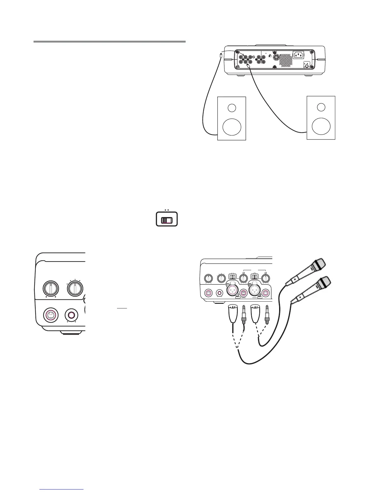
Setting Up Speakers
When using the built-in speaker, turn on
the SPEAKER switch. Turn off the
speaker when using headphones or
when connecting to powered speakers
or other sound equipment. Adjust
volume of the headphones or speaker by using the
PHONE/SPEAKER level knob.
The PHONE SELECTOR knob
determines which audio path will
be amplified/monitored through
the headphones and built-in
speaker. It does not affect any
audio being recorded. Use it to
monitor one of the following:
CD, AUX inputs, MIC/LINE inputs,
or LINE OUT which is a mix of the
CD drive or CD-R drive, and front
and rear panel inputs.
TIP:TIP:
TIP:TIP:
TIP: Typically, you will want to leave the PHONE
SELECTOR knob set on LINE OUT. Remember that
the LINE OUT level control affects the volume of
sound emanating from any external speakers.
Headphones or Built-In Speaker
SPEAKER
ON
OFF
REMOTE
IN
RC-5
OUT
EXT.
INT.
IN
OFF
ON/
POWER
OUT
DIGITAL
OUT
AUX
LINE
MIX
IN
PEDAL
FOOT
OUT
IN
L
R
Input
Level
Connect external powered speakers to the rear panel
RCA line outputs, making sure the Left channel line
output is securely attached to the speaker’s Left input
and the Right channel line output is securely attached
to the speaker’s Right input. (see Figure A.)
Or, similarly connect the L-R channel line outputs to the
L-R auxiliary or line inputs of a stereo amplifier that is
attached to speakers.
External Speakers
Fig A. - Powered Speaker Set Up
1. Set both front panel input switches to MIC. The left
switch is labeled LINE/MIC/INST and the right switch
is labeled LINE/MIC/INT MIC.
2. Plug microphones into either the XLR or 1/4” front
panel inputs, depending on your mic type
3. For condenser microphones that use batteries, make
sure the mic’s batteries are fresh. When using
microphones that require +48V phantom power,
connect mics to the XLR inputs and make sure that
the phantom power switch on the rear panel is ON.
4. See Setting Levels sidebar (pg. 12).
Set Up
- 11 -
INST
MIX
SPLIT
STEREO
MIC/LINE
ON
OFF
-20dB
LINE
MIC
LEFT
RIGHT
MIC/LINE
OPEN/CLOSE
SPEAKER
ALC/ATT
INPUT
ON
OFF
DIGITAL
ANALOG
PHONE SELECTOR
PHONE SELECTOR
MIC/LINE
LINE
CD
PHONE/SPEAKER
MIC/LINE
AUX
LINE OUT
LEVEL
PHONES
LINE OUT
LINE OUT
CD PLAY/RECORD
PUSH
NEUTRIK
PUSH
NEUTRIK