2-7
Installation and Commissioning
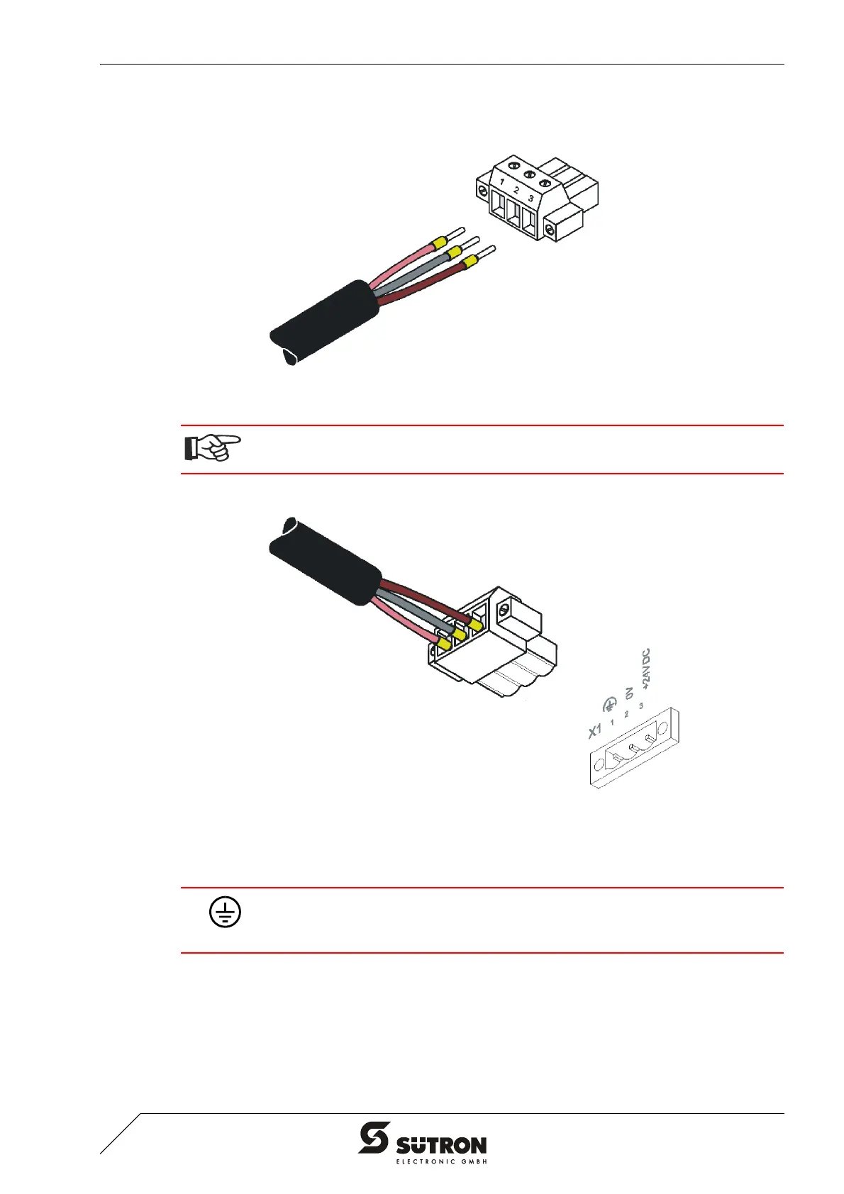
2. Fit the wires with wire end ferrules and connect the wires to the connector.
Figure 2-6 Connecting the female connector strip
3. Plug the female connector strip onto connector X1.A.
Figure 2-7 Female connector strip is plugged on
4. Secure the female connector strip in place with a screw-type locking to prevent
it from slipping out.
If shielded connecting cables are used in the supply voltage area, the shield should
be connected to pin 1.
A separate conductor must always be provided for the protective grounding at the
threaded bolt. The conductor must have a minimum cross-section of 1.5 mm² (16
AWG) and must be kept as short as possible.


 To Next Page