4-21
Interfaces of the Device
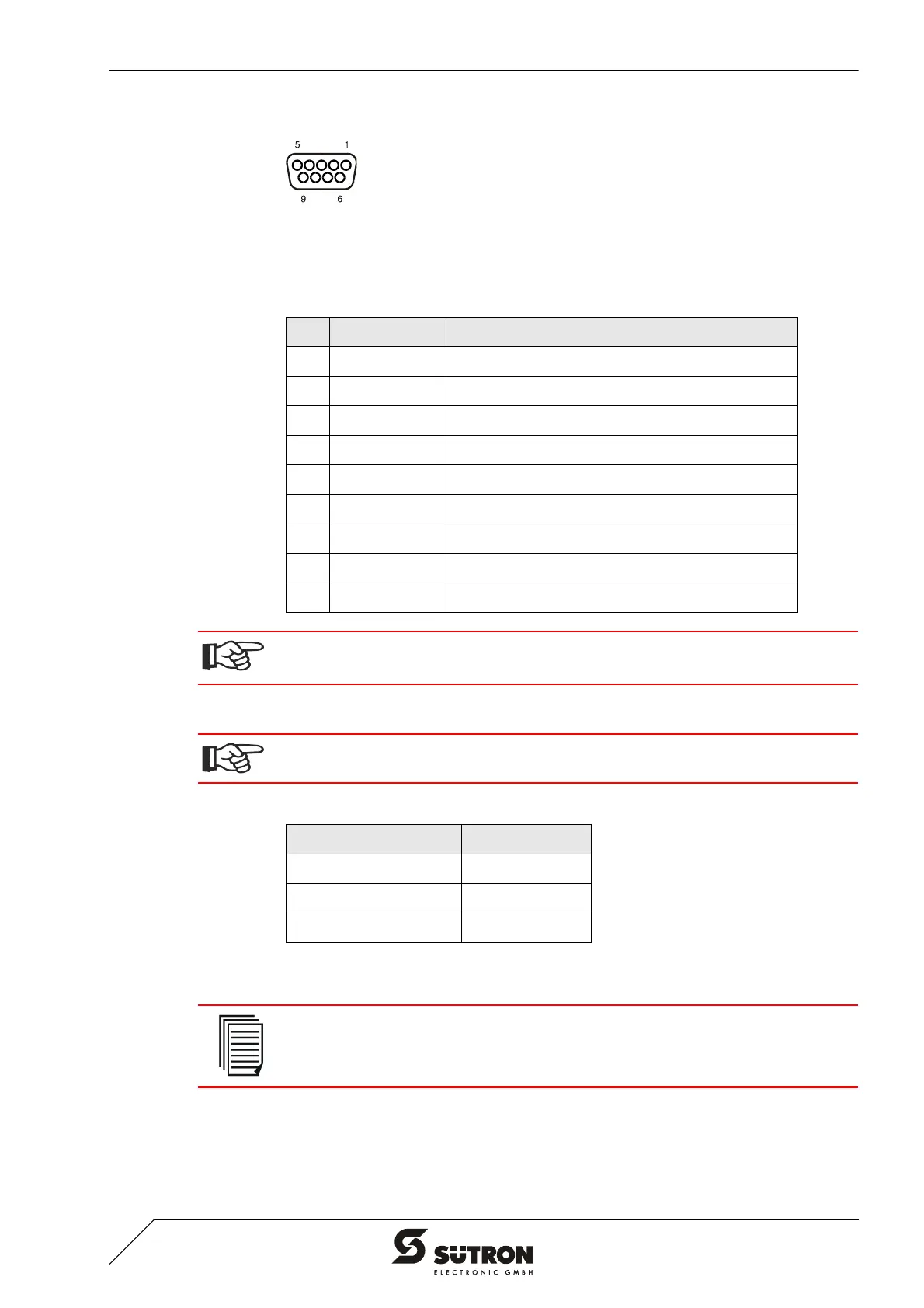
4.2.5.1 Pin Assignment
Figure 4-19 9 pin D-SUB female connector strip
Connector in the terminal: 9 pin D-SUB female connector
4.2.5.2 Cable
The maximum length of one segment is 50 m which cannot be exceeded. This 50 m
applies from the first node to the last node in the segment.
4.2.5.3 Termination
The bus line is terminated at the connector.
For point-to-point connections, always activate the termination. For multi-point con-
nections, only activate the termination at the cable end. For spur lines, always deac-
tivate the termination.
Table 4-22 Pin assignment MPI
Pin Designation Function
1 nc Not Connected
2 nc Not Connected
3 RxD/TxD-P Received Data / Transmitted Data Plus
4 CNTR-P Repeater Control Signal Plus
5 DGND Data Transmission Potential
6 VP Supply Voltage of Terminators Plus
7 nc Not Connected
8 RxD/TxD-N Received Data / Transmitted Data Minus
9 CNTR-N Repeater Control Signal Minus
The D-SUB connector strips must be shielded sufficiently.
See chapter “Shielding D-SUB Connectors“ on page 4-27.
Any cable that conforms with the following parameters can be used:
Table 4-23 Cable characteristics MPI
Parameters Value
Loop Resistance 110 Ohm/km
Capacitance 30 nF/km
Surge Impedance 150 Ohm
For further information on the installation, please refer to the Siemens manual "SI-
MATIC S7-400 and M7-400 Programmable Controllers Hardware and Installation,
6ES7498-8AA03-8BA0".
 Loading...