4-3
Interfaces of the Device
4.1.1 TTY / 20 mA Current Loop (X3-SER1)
Depending on the wiring, it is possible to connect the interface either as an active or
passive current loop. The transmit line and the receive line are each provided with a
separate 20 mA power source. The compliance voltage is approx. 10 VDC.
The 20 mA power should be supplied by the transmitter unit. This decreases
crosstalk on the signal lines considerably.
In idle state (signal logic 1), a 20 mA current loop can be measured in the cable.
4.1.1.1 Pin Assignment
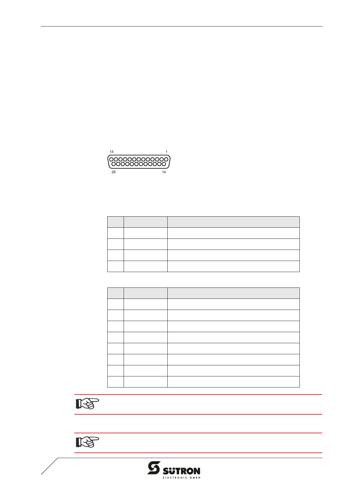
Figure 4-2 25 pin D-SUB female connector strip
Connector in the terminal: 25 pin D-SUB female connector strip.
4.1.1.2 Termination
Signal Logic 1 Current Flow 20 mA
Signal Logic 0 Current Flow Interrupted
Table 4-2 Pin assignment TTY / 20 mA, passive
Pin Designation Function
10 T+ Transmitted Data, Positive Polarity
13 R+ Received Data, Positive Polarity
14 R- Received Data, Negative Polarity
19 T- Transmitted Data, Negative Polarity
Table 4-3 Pin assignment TTY / 20 mA, active
Pin Designation Function
10 T+ Transmitted Data, Positive Polarity
12 S1+ Power Source 1, Positive Polarity
13 R+ Received Data, Positive Polarity
14 R- Received Data, Negative Polarity
16 S2+ Power Source 2, Positive Polarity
19 T- Transmitted Data, Negative Polarity
21 S1- Current Sink 1, Negative Polarity
24 S2- Current Sink 2, Negative Polarity
The D-SUB connector strips must be shielded sufficiently.
See chapter “Shielding D-SUB Connectors“ on page 4-27.
For the operation of channel SER1 as a current loop, the termination for the RS485
must be deactivated.


 To Next Page