Interfaces of the Device
4-12
1. Fastening Screw
2. Cable Fastener for Battery
3. Seal
4. Front Panel
5. Mounting Bolt
6. Nameplate
7. Threaded Bolt for Protective Grounding
8. Connector X1.A (Supply Voltage)
9. Reset Key
10. User Mode Switch
11. Connector X2.1 (DeviceNet)
12. Assignment Connector X2.1 (DeviceNet)
13. Female Connector X3 (SER2 RS232c)
14. Female Connector X2.2 (DeviceNet)
15. Assignment Female Connector X2.2 (DeviceNet)
16. Compact Flash, Inserted on the Side (Option)
17. Diagnostics LED
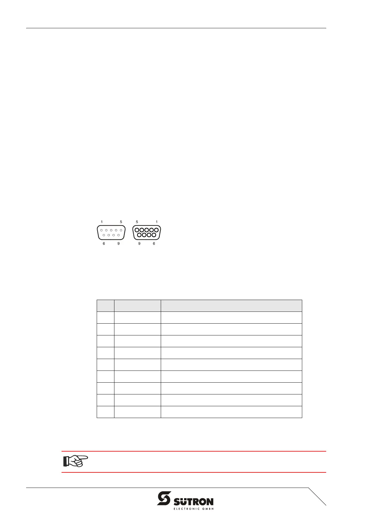
4.2.2.1 Pin Assignment
Figure 4-11 9 pin D-SUB male connector strip and female connector strip
Connector in the terminal: 9 pin D-SUB male and female connector strip (assignment
for male and female connector strip is the same.)
All signal lines are looped through from X2.1 to X2.2. The connecting cables should
be connected to every pin, including the reserved pins. In this way, the cables can
still be used in case of future bus specification extensions.
Table 4-13 Pin assignment CAN bus
Pin Designation Function
1 nc Not Connected
2 CAN_L CAN_L Bus Line (Dominant LOW)
3 CAN_GND CAN Ground
4 nc Not Connected
5 nc Not Connected
6 CAN_GND CAN Ground
7 CAN_H CAN_H Bus Line (Dominant HIGH)
8 nc Not Connected
9 nc Not Connected
The D-SUB connector strips must be shielded sufficiently.
See chapter “Shielding D-SUB Connectors“ on page 4-27.
 Loading...