Interfaces of the Device
4-4
4.1.2 RS485 (X3-SER1)
The interface is suitable for point-to-point and for multi-point connections.
The wires belonging together are marked with „A“ and „B“. Some descriptions refer
to the pins with „+“ and „-“ , where A = + and B = -.
4.1.2.1 Pin Assignment
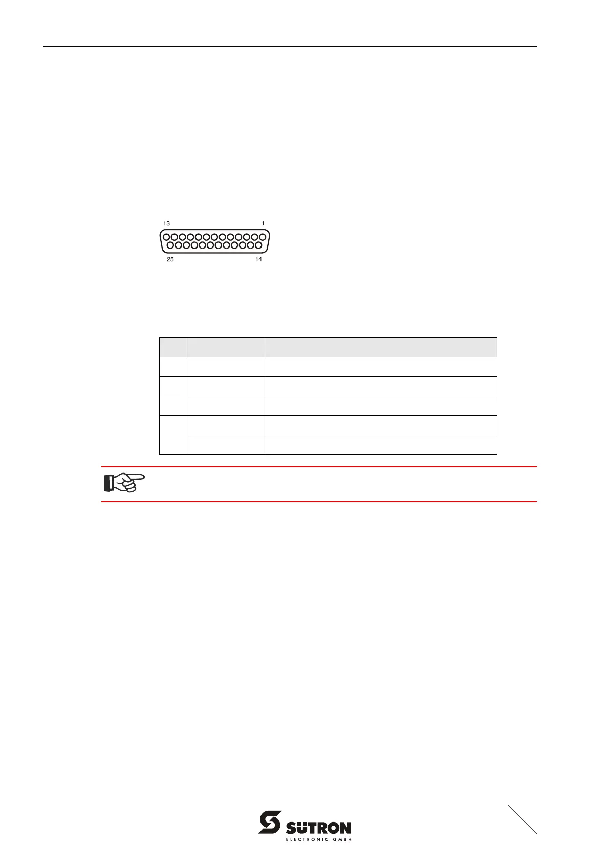
Figure 4-3 25 pin D-SUB female connector strip
Connector in the operating terminal: 25-pin D-SUB female connector
Signal Logic 1 U
A
- U
B
<= -0.3 V i.e. (U
A
< U
B
)
Signal Logic 0 U
A
- U
B
>= +0.3 V i.e. (U
A
> U
B
)
Table 4-4 Pin assignment RS422/RS485
Pin Designation Function
8 T(A) Transmitted Data (+)
9 T(B) Transmitted Data (-)
11 SGND Signal Ground
22 R(A) Received Data (+)
23 R(B) Received Data (-)
The D-SUB connector strips must be shielded sufficiently.
See chapter “Shielding D-SUB Connectors“ on page 4-27.


 To Next Page