Interfaces of the Device
4-24
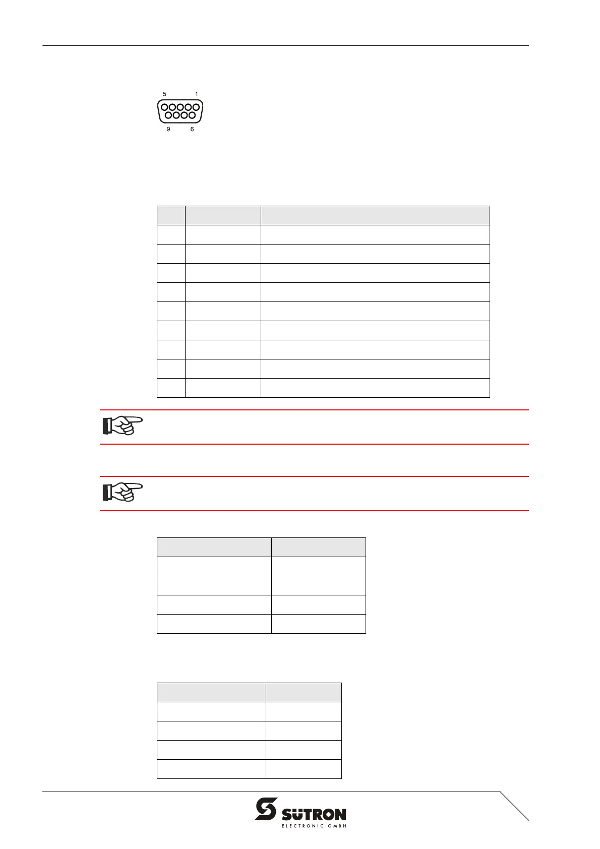
4.2.6.1 Pin Assignment
Figure 4-22 9 pin D-SUB female connector strip
Connector in the operating device: 9 pin D-SUB female connector.
4.2.6.2 Cable
The maximum cable length depends on the baud rate (DIN EN 19245 Part 3).
Table 4-25 Pin assignment PROFIBUS-DP
Pin Designation Function
1 nc Not Connected
2 nc Not Connected
3 RxD/TxD-P Received Data / Transmitted Data Plus
4 CNTR-P Repeater Control Signal Plus
5 DGND Data Transmission Potential
6 VP Supply Voltage of Terminators Plus
7 nc Not Connected
8 RxD/TxD-N Received Data / Transmitted Data Minus
9 CNTR-N Repeater Control Signal Minus
The D-SUB connector strips must be shielded sufficiently.
See chapter “Shielding D-SUB Connectors“ on page 4-27.
Any PROFIBUS-DP-approved cables specified in the EN 50170 as cable type A can
be used.
Table 4-26 Cable characteristics PROFIBUS
Parameters Value
Impedance 136 to 165 Ohm
Capacitance < 30 pf/m
Loop Resistance 110 Ohm/km
Wire Gauge 0.64 mm
Table 4-27 Baud rate PROFIBUS-DP
Baud Rate Cable Length
187.5 kBit/s 1000 m
500 kBit/s 400 m
1500 kBit/s 200 m
3000 to 12000 kBit/s 100 m