4-13
Interfaces of the Device
4.2.2.2 Cable
The maximum length allowed for spur lines connected to the bus cable is 6 meters.
The overall length of the bus cable including all spur lines is not to exceed the max-
imum length listed in the table below.
The maximum cable length depends on the baud rate and the cable type used.
4.2.2.3 Termination
Terminate the CAN bus at both ends directly at the connector by terminating resistors
(120 Ohm).
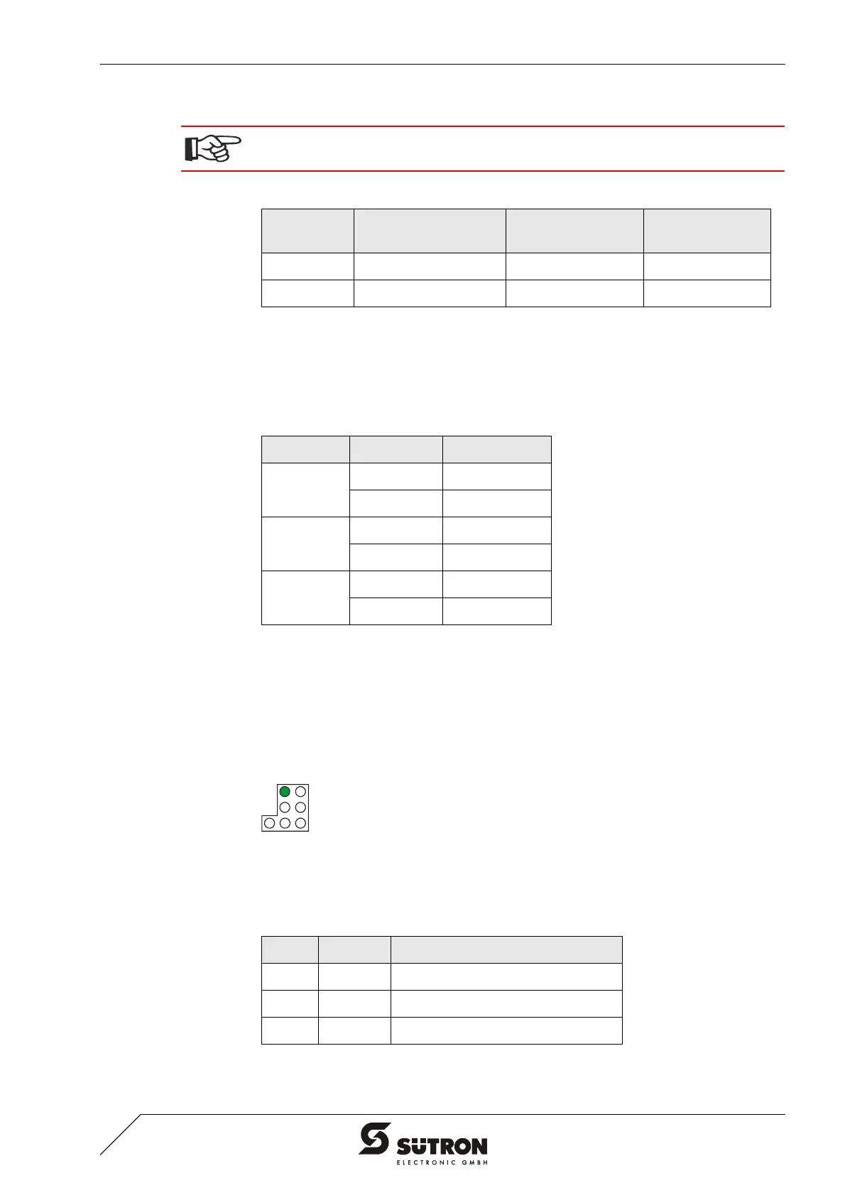
4.2.2.4 Diagnostic
A diagnostics LED is located at the rear of the operating device. The LED shows the
states of the bus system.
Figure 4-12 Arrangement of the DeviceNet diagnostics LED
The diagnostics LED at the operating device has the following functions:
A DeviceNet-certified cable must be used.
Table 4-14 Data line DeviceNet
Cable Type Loop Resistance Surge Impedance Capacitance per
Unit Length
2 x 1.1 mm < 22.6 Ohm/km 120 Ohm < 39.4 pf/m
2 x 0.6 mm < 91.8 Ohm/km 120 Ohm < 39.4 pf/m
Table 4-15 Baud rate DeviceNet
Baud Rate Cable Type Cable Length
125 kBit/s 2 x 1.1 mm 500 m
2 x 0.6 mm 100 m
250 kBit/s 2 x 1.1 mm 250 m
2 x 0.6 mm 100 m
500 kBit/s 2 x 1.1 mm 100 m
2 x 0.6 mm 100 m
Table 4-16 Function of the CAN diagnostics LED
Color State Function
Green Off Terminal Disconnected from Bus
Green On Communication Active
Green Flashing Sporadic Bus Error