Interfaces of the Device
4-18
4.2.4.1 Connector Pin Assignment
The optical fiber interface is designed as a FSMA type 905.
4.2.4.2 Cable
The cables are connected in accordance with the "INTERBUS Fiber Optic Installa-
tion Guidelines".
Suitable for optical transmission is a dielectric waveguide with step index refractive
index profile - a polymer fiber with a core diameter of 980 µm and a cladding diameter
of 1000 µm. The F-SMA connector is specified in IEC 874-2 or in DIN 47258, respec-
tively.
The maximum distance between two remote bus users is 50 m (164.042 ft.).
4.2.4.3 Diagnostic
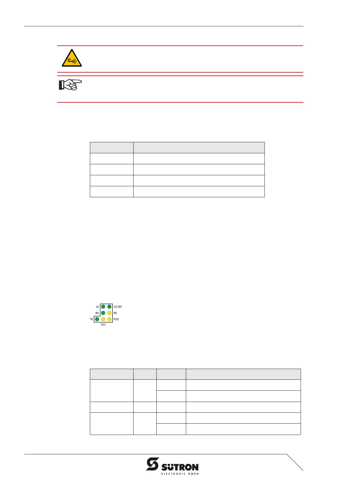
The diagnostics LEDs are located at the rear of the operating device. The LEDs show
the states of the bus system.
Figure 4-17 Arrangement of the INTERBUS OPC LWL diagnostics LEDs
The diagnostics LEDs at the operating device has the following functions:
Never look directly into the open end of an optical fiber cable. Infrared light can
cause damage to the retina of the eye. Fit the open ends of an optical fiber cable
and the connections with protective caps. Wear protective goggles.
The sending and receiving units can be rendered unusable by dirt accumulation. For
this reason, place protective caps onto the connections when the units are not used
or are transported! Wear protective goggles.
Table 4-20 Assignment INTERBUS OPC LWL
Designation Function
DO1 Remote Bus In
DI1 Remote Bus In
DO2 Remote Bus Out
DI2 Remote Bus Out
Table 4-21 Functions of the INTERBUS OPC LWL diagnostics LEDs
Designation Color State Function
UL Green On Supply Voltage OK
Off No Supply Voltage
CC/RC Green On Remote Bus Cable Check
BA Green On Bus Active
Off Bus Not Active


 To Next Page