Interfaces of the Device
4-14
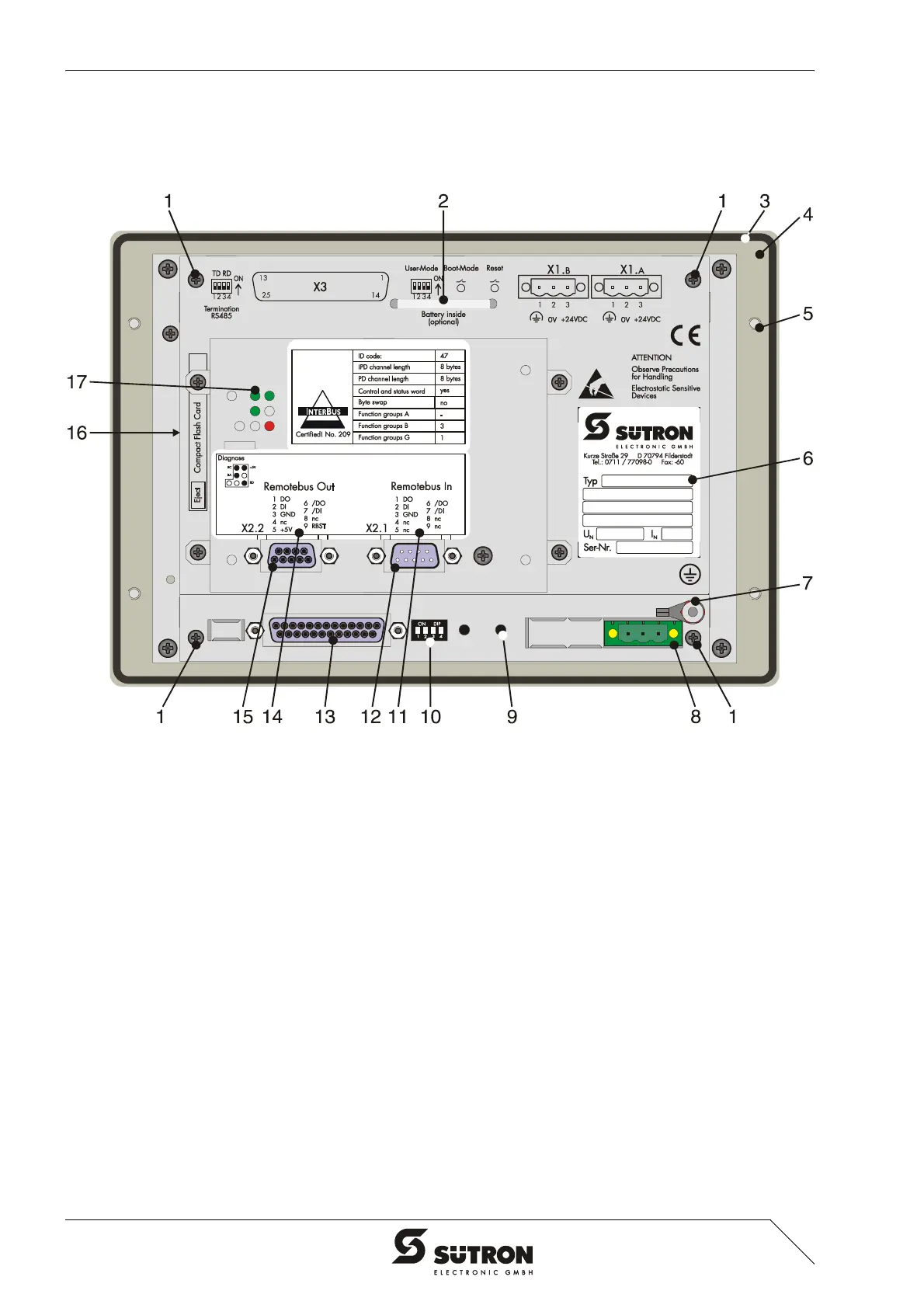
4.2.3 INTERBUS (X2.1/X2.2)
The device can be integrated into the INTERBUS using the interfaces available for
INTERBUS connections.
Figure 4-13 Rear view INTERBUS
1. Fastening Screw
2. Cable Fastener for Battery
3. Seal
4. Front Panel
5. Mounting Bolt
6. Nameplate
7. Threaded Bolt for Protective Grounding
8. Connector X1.A (Supply Voltage)
9. Reset Key
10. User Mode Switch
11. Assignment Connector X2.1 (Remote Bus In)
12. Connector X2.1 (Remote Bus In)
13. Female Connector X3 (SER2 RS232c)
14. Assignment Female Connector X2.2 (Remote Bus Out)
15. Female Connector X2.2 (Remote Bus Out)
16. Compact Flash, Inserted on the Side (Option)
17. Diagnostics LEDs
 Loading...