4-15
Interfaces of the Device
4.2.3.1 Pin Assignment
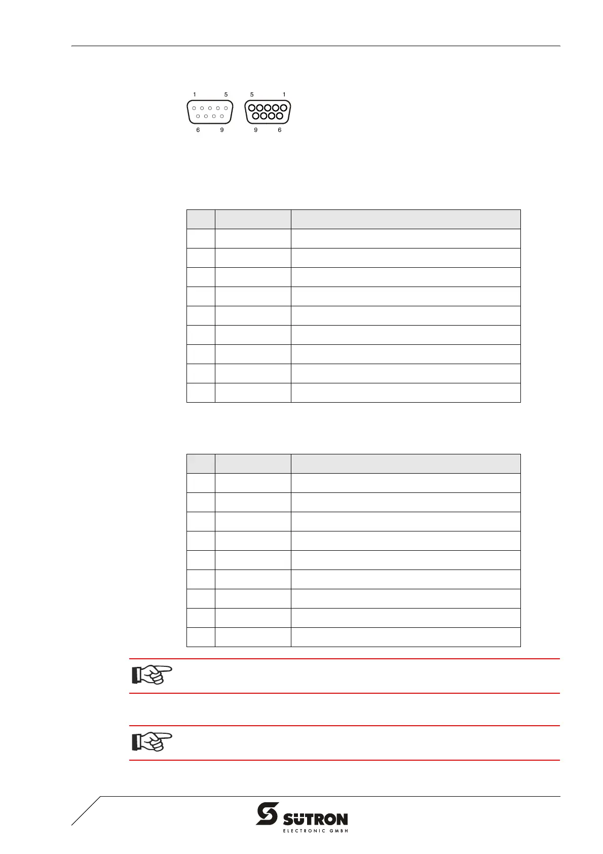
Figure 4-14 9 pin D-SUB male connector strip and female connector strip
Connector in the terminal: 9 pin D-SUB male connector strip for remote bus in.
Connector in the terminal: 9 pin D-SUB female connector strip for remote bus out.
4.2.3.2 Cable
Table 4-17 Pin assignment remote bus in (INTERBUS)
Pin Designation Function
1 DO Data Input
2 DI Data Output
3 GND Ground
4 nc Not Connected
5 nc Not Connected
6 /DO Data Input, Inverted
7 /DI Data Output, Inverted
8 nc Not Connected
9 nc Not Connected
Table 4-18 Pin assignment remote bus out (INTERBUS)
Pin Designation Function
1 DO Data Output
2 DI Data Input
3 GND Ground
4 nc Not Connected
5 +5 V Power Supply +5 VDC
6 /DO Data Output, Inverted
7 /DI Data Input, Inverted
8 nc Not Connected
9 RBST Remote Bus Status
The D-SUB connector strips must be shielded sufficiently.
See chapter “Shielding D-SUB Connectors“ on page 4-27.
A shielded twisted-pair cable (cable type LiYCY-TP) must be used. The maximum
cable length depends on its use within the INTERBUS topology.
 Loading...