Interfaces of the Device
4-10
4.2.1.2 Cable
The cable must have the following characteristics:
The maximum cable length depends on the baud rate used.
4.2.1.3 Termination
Terminate the CAN bus at both ends by terminating resistors (120 Ohm).
4.2.1.4 Diagnostic
A diagnostics LED is located at the rear of the operating device. The LED shows a
state of the bus system.
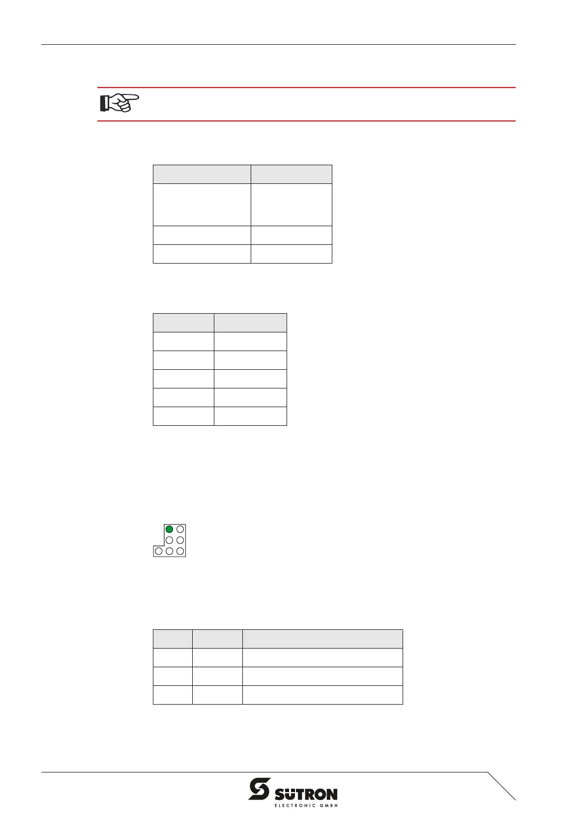
Figure 4-9 Arrangement of the CAN diagnostics LED
The diagnostics LED at the operating device has the following functions:
A shielded twisted-pair cable (cable type LiYCY-TP) complying with ISO 11898 must
be used.
Table 4-10 Cable characteristics CAN
Parameters Value
Impedance Min.: 108 Ohm
Nom.: 120 Ohm
Max.: 132 Ohm
Specific Resistance 70 mOhm/m
Specific Line Delay 5 ns/m
Table 4-11 Baud rate CAN
Baud rate Cable length
20 kBit/s 1000 m
125 kBit/s 500 m
250 kBit/s 250 m
500 kBit/s 100 m
1000 kBit/s 25 m
Table 4-12 Function of the CAN diagnostics LED
Color State Function
Green Off Terminal Disconnected from Bus
Green On Communication Active
Green Flashing Sporadic Bus Error
 Loading...