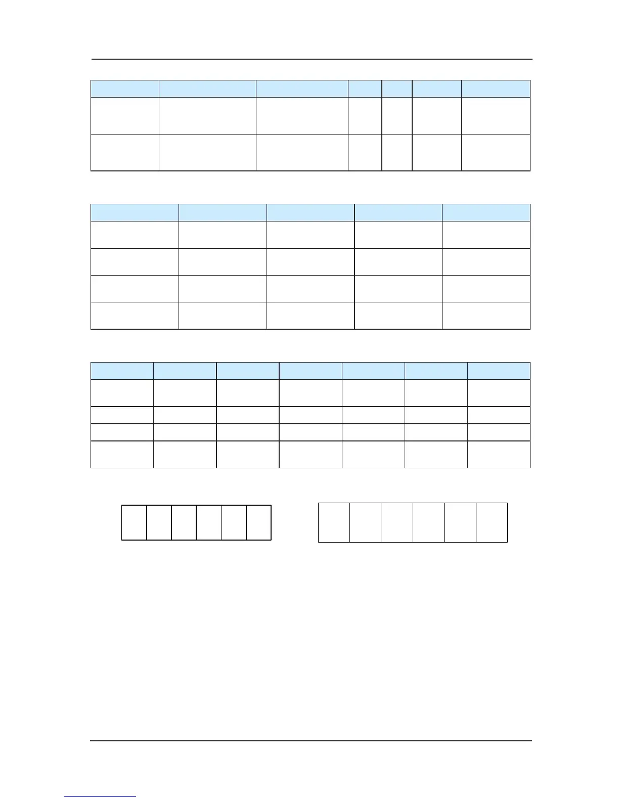
S1.1~S1.5 S2.1 S2.2 S2.3 S2.4 S2.5
7 segment
code function
Floor address
setting,range:0~31
MOD bus
terminal matching
resistance setting
OFF OFF Detection
Floor address
setting
Voice station
report
S1.1~S1.3oor
setting
S1.4,S1.5
MOD-bus
terminal matching
resistance setting
ON ON Detection Reserved
Table 1
K1 K2 K3 K4
HCB-B Up arrival lamp
Down arrival
lamp
Up arrival gong
Down arrival
gong
HPB
Overload/full-
load
Reserved Up indicate Down indicate
7 segment
function
G
Overload/full
load
Up indicate Down indicate
Voice station
report
Overload/full
load
Arrival output Up output Down output
Table 2
C1 C2 C3 C4 C5 C6
Common
terminal
BM BM BM BM BM BM
HPB, F0 F1 F2 F3 F4 负号
7 segment A B C D E F
Voice station
report
Floor binary
bit0
Floor binary
bit1
Floor binary
bit2
Floor binary
bit3
Reserved Reserved
Table 3 open collector output binary oor display
Fig3-9 CN2 terminal definition Fig 3-10 CN3 terminal definition
HCB-B function 1)
Totally compatible for the original HCB-B function
The definitions of the dial-code switch bits are as the table 1.
The oor address is the valid oors (standard as the leveling plate) increased down to up, and
it has no relations with the actual oor numbers.
For instance, if a building has 2 oor basem
ent, 10 oors above the earth, and the 3rd and 4th
oor are the non-service oor, then the oor address setting is: the 2nd oor of basement set as
1; the 1st oor of the basement set as 2; the 1st oor above the earth set as 3, 2nd oor above
set as 4, and if there is leveling plate in the 3rd and 4th oor, then set them as 5,6. From the
 Loading...