FUEL AND LUBRICATION SYSTEM 4-15
REMOUNTING
Remount the carburetor assembly in the reverse order of re-
moval. After the carburetor assembly has been remounted onto
the engine perform the following adjustments:
Throttle cable play.................................................. 2-13
Engine idle speed .................................................. 2-14
Ω
1
Ω
2
Bl
Y
B
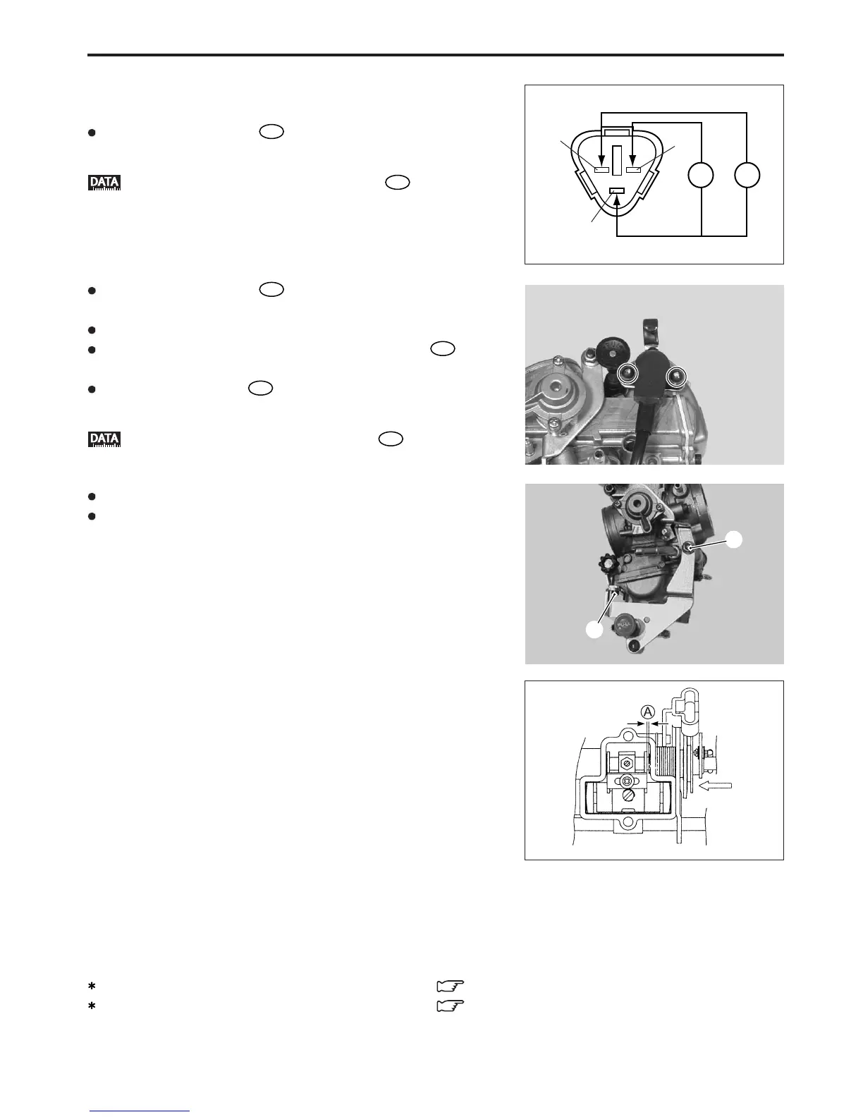
THROTTLE POSITION SENSOR INSTALLATION
Install the throttle position sensor as described below.
Measure the resistance
Ω1
between the throttle position sen-
sor terminals as shown in the illustration.
Throttle position sensor resistance
Ω1
:
Approximately 5 k
ΩΩ
ΩΩ
Ω
Measure the resistance
Ω2
between the throttle position sen-
sor terminals as shown in the illustration.
Fully open the throttle valve with the throttle lever.
Position the throttle position sensor until resistance
Ω2
is 3.09
– 4.63 kΩ.
When the resistance
Ω2
is within specification, tighten the
throttle position sensor mounting screws.
Throttle position sensor resistance
Ω2
:
3.09 – 4.63 k
ΩΩ
ΩΩ
Ω
Install the air valve assembly.
First tighten the bolt 3 and then tighten the nut 4.
(DR-Z400)
Keep the clearance A (0.5 – 0.7 mm) between rink arm and
carburetor body when pushing the throttle lever as shown.
A: Clearance 0.5 – 0.7 mm
If the clearance is out of specification, adjust the clearance.