4A-8 Brake Control System and Diagnosis:
Front Brake Hose Removal and Installation
B649G14106025
Removal
1) Drain brake fluid. Refer to “Brake Fluid
Replacement: ”.
2) Remove the front brake hoses as shown in the front
brake hose routing diagram. Refer to “Front Brake
Hose Routing Diagram: ”.
Installation
CAUTION
!
The seal washers should be replaced with the
new ones to prevent fluid leakage.
1) Install the front brake hose as shown in the front
brake hose routing diagram. Refer to “Front Brake
Hose Routing Diagram: ”.
2) Bleed air from the front brake system. Refer to “Air
Bleeding from Brake Fluid Circuit: ”.
Rear Brake Hose Removal and Installation
B649G14106026
Removal
1) Remove right frame cover. Refer to “Exterior Parts
Removal and Installation: in Section 9D”.
2) Drain bracket fluid. Refer to “Brake Fluid
Replacement: ”.
3) Remove the rear brake hose as shown in the rear
brake hose routing diagram. Refer to “Rear Brake
Hose Routing Diagram: ”.
Installation
CAUTION
!
The seal washers should be replaced with the
new ones to prevent fluid leakage.
1) Install the rear brake hose as shown in the rear
brake hose routing diagram. Refer to “Rear Brake
Hose Routing Diagram: ”.
2) Bleed air from the rear brake system. Refer to “Air
Bleeding from Brake Fluid Circuit: ”.
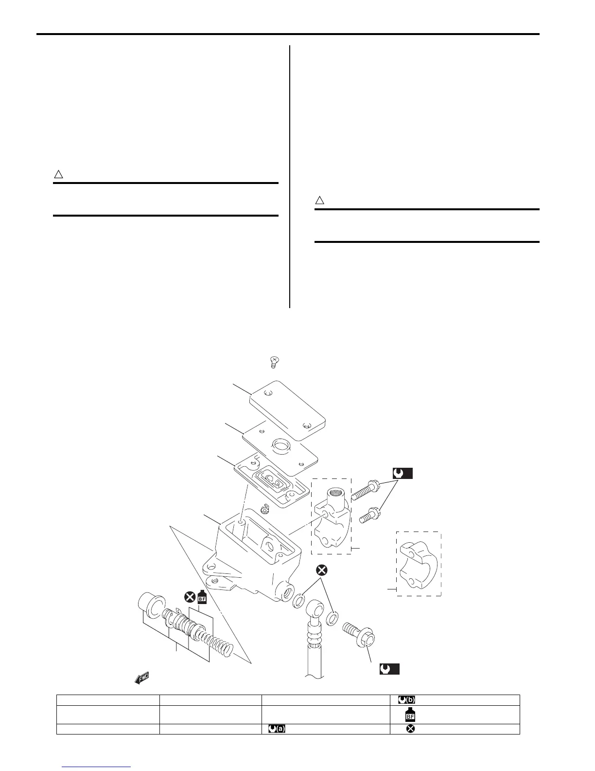
Front Brake Master Cylinder Components
B649G14106027
1
2
3
4
(a)
6,
[B]
[A]
5
(b)
I649G1410014-04
1. Reservoir cap 4. Master cylinder [A]: For GSF1200 : 10 N⋅m (1.0 kgf-m, 7.0 lb-ft)
2. Plate 5. Piston/Cup set [B]: For GSF1200S : Apply brake fluid.
3. Diaphragm 6. Brake hose union bolt : 23 N⋅m (2.3 kgf-m, 16.5 lb-ft) : Do not reuse.
 Loading...