Engine Mechanical: 1D-47
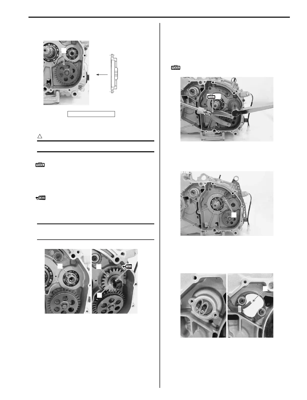
• Install the oil pump driven gear (4) as shown in the
figure.
• Install new snap ring.
CAUTION
!
Never reuse the removed snap ring.
Special tool
: 09900–06107 (Snap ring pliers)
• Install the pin (5).
• Install the oil pump drive gear (6) and washer (7).
• Apply thread lock to the oil pump drive gear bolt.
: Thread lock cement 99000–32030
(THREAD LOCK CEMENT SUPER 1303 or
equivalent)
NOTE
Flange side of the oil pump drive gear is
positioned inside.
• Tighten the oil pump drive gear bolt to the specified
torque with the special tool.
Tightening torque
Oil pump drive gear bolt: 80 N·m (8.0 kgf-m, 58.0
lb-ft)
Special tool
(A): 09930–40113 (Rotor holder)
Cam Chain
• Install the cam chain (1).
Gear Position Switch
• Install the springs and switch contacts.
• Install the gear position switch (1).
“A”: Crankcase side
4
“A”
I827H1140167-01
6
7
5
I827H1140168-01
(A)
I827H1140169-01
1
I827H1140170-01
1
I827H1140171-01

 Loading...


