6-1-80 ENGINE GENERAL INFORMATION AND DIAGNOSIS (SFI FOR G13)
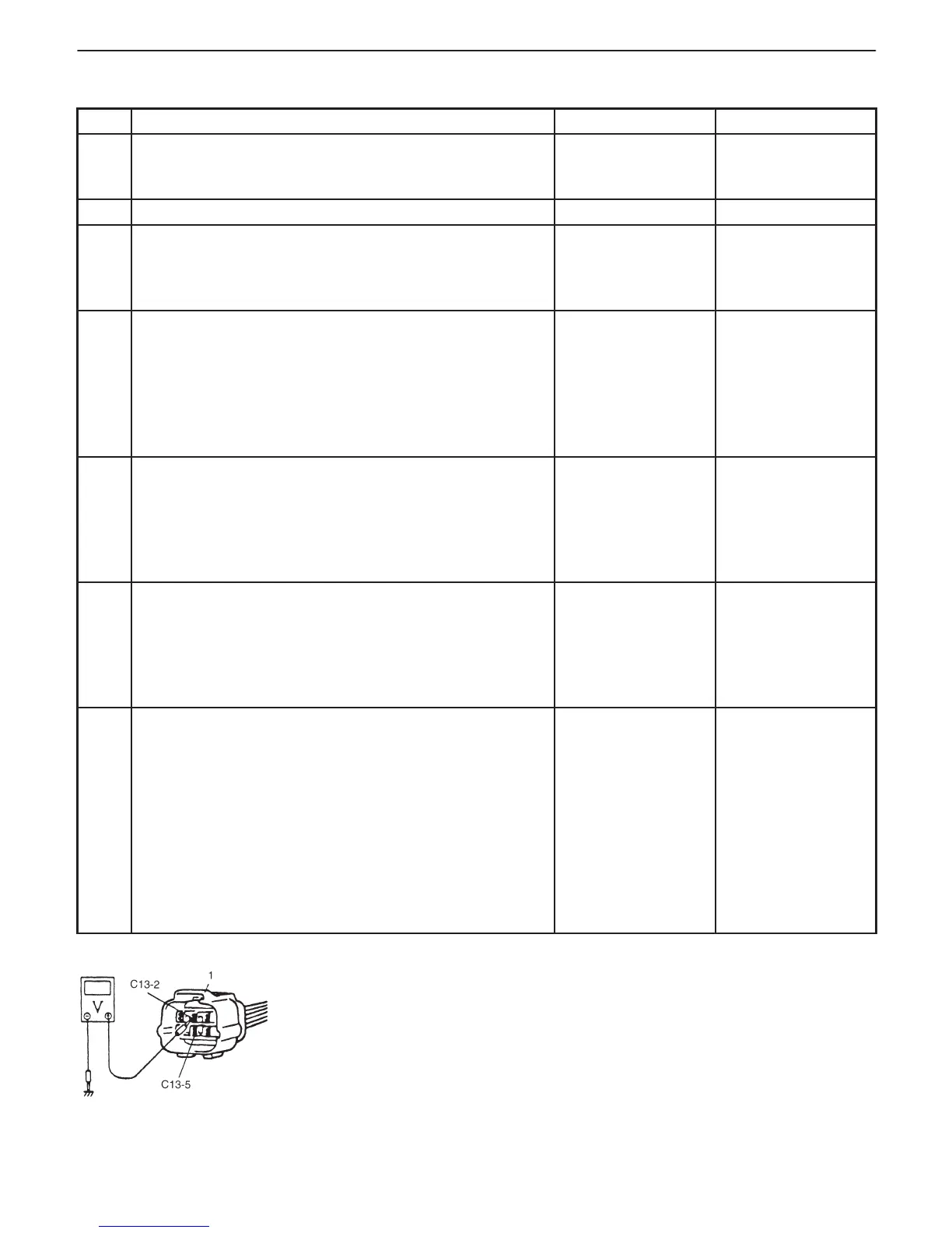
1. EGR valve coupler
INSPECTION
STEP ACTION YES NO
1 Was ENGINE DIAG. FLOW TABLE performed? Go to Step 2. Go to ENGINE
DIAG. FLOW
TABLE.
2 Do you have SUZUKI scan tool? Go to Step 3. Go to Step 5.
3 EGR Valve Operation Check
1) With ignition switch OFF, install SUZUKI scan tool.
2) Check EGR system referring to section 6E2.
Is it in good condition?
Go to Step 4. Go to Step 5.
4 MAP Sensor Check
1) Check MAP sensor for performance referring to “MAP
Sensor Check” in DTC P0105 Diag. Flow Table.
Is check result satisfactory?
Intermittent trouble
or faulty ECM
(PCM) Check for in-
termittent referring
to “Intermittent and
Poor Connection” in
section 0A.
Repair or replace.
5 EGR Valve Power Supply Circuit Check
1) With ignition switch OFF, disconnect EGR valve
coupler.
2) With ignition switch ON, check voltage between C13-2
and ground, C13-5 and ground. See Fig. 1.
Is each voltage 10 – 14 V?
Go to Step 6. “R/B” wire.
6 EGR Valve Stepping Motor Coil Circuit Check
1) With ignition switch OFF, connect EGR valve coupler
and disconnect ECM (PCM) couplers.
2) Check resistance between C02-6 and C02-2, C02-8,
C02-9, C02-17.
Is each resistance 20 – 24 Ω at 20_C, 68_F?
Go to Step 7. Faulty “R/Y”,
“R/Bl”, “R”, “R/W”
wire or EGR valve.
7 MAP Sensor Check
1) Check MAP sensor for performance referring to
“MAP Sensor Check” in DTC P0105 Diag. Flow Table.
Is check result satisfactory?
EGR passage
clogged or EGR
valve malfunction.
If all above are OK,
intermittent trouble
or faulty ECM.
Check for intermit-
tent referring to
“Intermittent and
Poor Connection” in
section 0A.
Repair or replace.
Fig. 1 for step 5