ENGINE GENERAL INFORMATION AND DIAGNOSIS (SFI FOR G13) 6-1-105
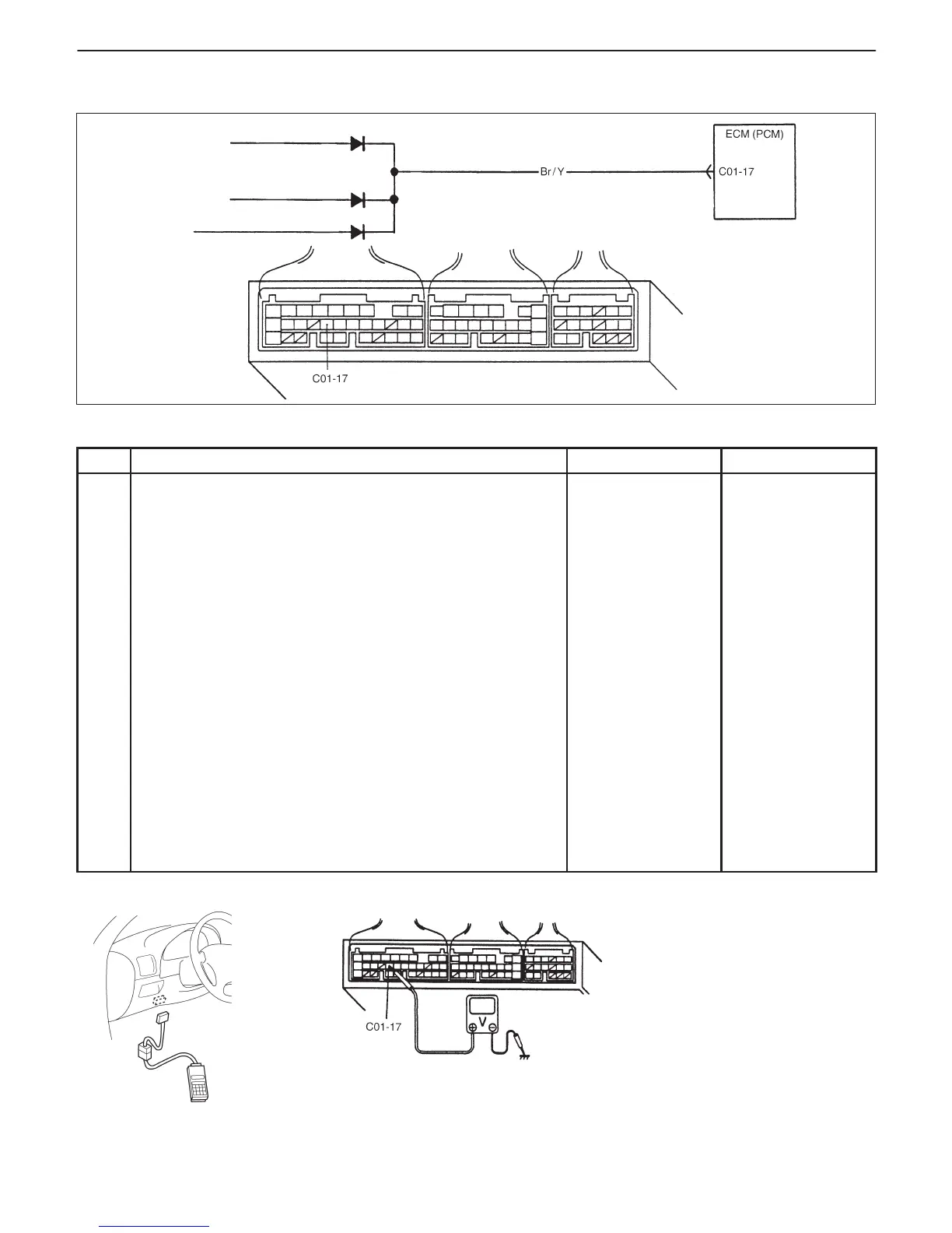
Heater blower
switch
Rear defogger
switch
Tail light relay
(Lighting switch)
Diodes in junction/
fuse block
Fig. 1 for Step 1 Fig. 2 for Step 1
TABLE B-6 ELECTRIC LOAD SIGNAL CIRCUIT CHECK
INSPECTION
STEP ACTION YES NO
1 Check Electric Load Signal Circuit.
When using SUZUKI scan tool:
1) Connect SUZUKI scan tool to DLC with ignition
switch OFF.
2) Start engine and select “DATA LIST” mode on
scan tool.
3) Check electric load signal under following each
condition. See Fig. 1.
Ignition switch ON, Small light,
heater blower fan and rear
defogger all turned OFF : OFF
0 V (C01-17)
Ignition switch ON, Small light,
heater blower fan or rear
defogger turned ON : ON
10 – 14 V (C01-17)
Is check result satisfactory?
When not using SUZUKI scan tool:
1) Turn ignition switch ON.
2) Check voltage at terminals C01-17 of ECM (PCM)
connector connected, under above each condition.
See Fig. 2.
Is each voltage as specified?
Electric load signal
circuit is in good
condition.
“Br/Y” circuit open
or short, Electric
load diodes
malfunction or
Each electric load
circuit malfunction.