Electrical systems
59
2.5 Control Panel Operation
• Power Button. Press the power button to
turn the leisure power on. Press the button
again to turn the power off. The adjacent
LED will illuminate when the power is on,
and also the voltage of the selected battery
will be displayed on the voltage gauge.
• Pump Button.
With the power on, press the pump button
to turn the water pump on. Press the button
again to turn the pump off. The adjacent
LED will illuminate when the pump is on,
and also the level of the water tank will be
displayed on the water gauge.
• Water Level Indicator.
For caravans with ana internal fresh water
tank, a warning will sound if the water level
drops below 25%. The fresh water gauge
LED will also light. To cancel the warning,
press the levels button.
• View Levels.
Press and hold the view levels button to
permanently display the level conditions.
To display the battery voltage levels and
the water tank levels on the control panel
gauges, press the levels button.
The display will remain illuminated for
10 seconds.
• Battery Select.
By default, the leisure battery is selected
as the power source if no mains supply is
present, or as the battery to be charged
when the mains supply is available. To
change the selected battery, press the
battery select button. The selected battery
is indicated by an LED adjacent to the
caravan or car logo (for caravans) or the
LED situated in the centre of the leisure and
vehicle battery gauges.
2.6 Operation while driving
The EC Series system is designed to shutdown
parts of the system while the engine is running.
This is to meet Electro Magnetic Compatibility
(EMC) regulations and to ensure the safe
operation of the caravan.
Please ensure the system isolation switch on
the PSU is in the on (button in) position before
driving (see 2.2). This will ensure the electronic
system is active and will therefore be able
to control the charging process, supply the
refrigerator and monitor other system circuits.
3. System Technical Information
The following section provides further technical
information relating to the electrical system.
You can also access the supporting technical
manual from www.sargentltd.co.uk
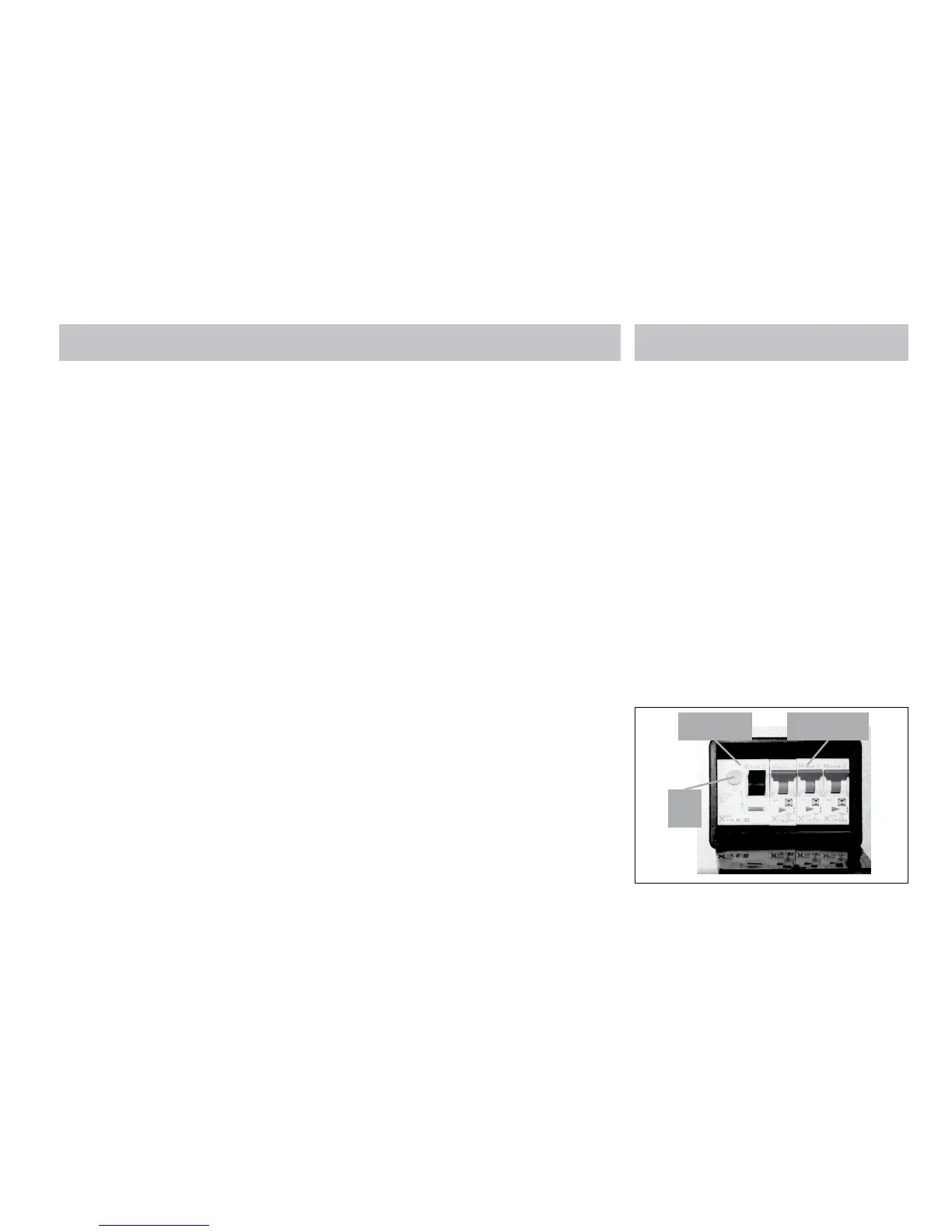
3.1 Residual Current Device & Miniature
Circuit Breakers
The Residual Current Device (RCD) is provided
to protect the user from lethal electric shock.
The RCD will turn off (trip) if the current flowing
in the live conductor does not fully return
down the neutral conductor, i.e. some current
is passing through a person down to earth or
through a faulty appliance.
To ensure the RCD is working correctly, the
test button should be operated each time the
vehicle is connected to the mains supply (see
section 2.3).
The Miniature Circuit Breakers (MCB’s) operate
in a similar way to traditional fuses and are
provided to protect the wiring installation from
overload or short circuit. If an overload occurs
the MCB will switch off the supply. If this
occurs you should investigate the cause of the
fault before switching the MCB back on.
Residual Current
Device (RCD)
Miniature Circuit
Breakers (MCB’s)
RCD
Test
button