Equipment details
79
Cleaning
(with switched off appliance!) We recommend
removing dust which has collected on the heat
exchanger and base plate of the heater and on
the impeller wheel of the Trumavent fan, once
a year before the heating season starts. Clean
the impeller wheel carefully using a brush or
tooth brush.
Blown air ducts
The air ducting outlets are generally of the
butterfly type and may be opened or closed
to control the quantity of air by adjusting the
butterfly valves. Twisting the disc in its housing
directs the flow in the direction required.
For uniform distribution, outlets nearest the
heater should be closed more than those
further away.
One outlet on each leg of the air ducting layout
must be kept open at all times.
Under no circumstances should the air ducting
outlets be blocked.
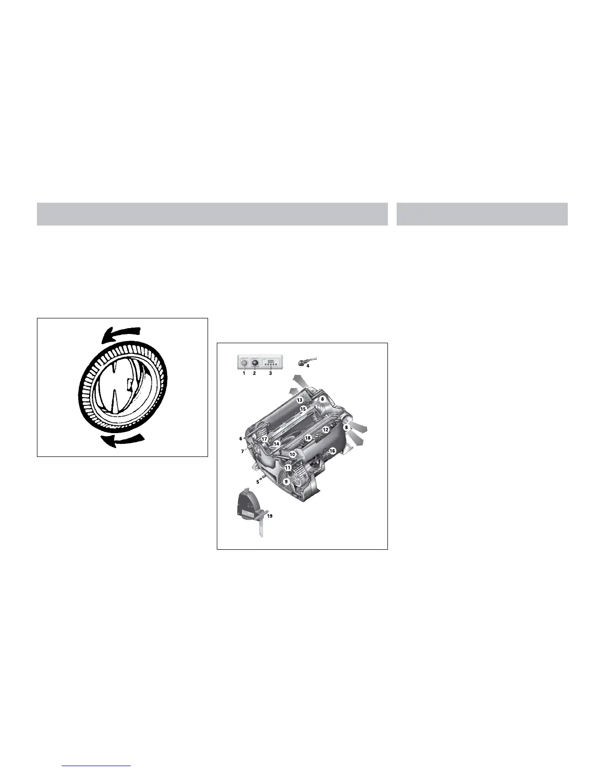
TRUMA COMBI 4 / COMBI 6
1 Control panel
2 Power selector switch
3 Time switch ZUCB (Accessories)
4 Room temperature sensor
5 Cold water connection
6 Hot water connection
7 Gas connection
8 Hot air outlets
9 Recirculated air intake
10 Waste gas discharge
11 Combustion air infeed
12 Electronic control unit
13 Water container (10 litres)
14 Burner
15 Heat exchanger
16 Power electronics
17 Heating elements 230 V
18 Overheating switch 230 V
19 FrostControl (safety/drain valve)
Function description
The liquid gas heater Combi E is a warm-air
heater with integrated hot water boiler (10 liter
volume). The burner operates fan-supported,
which ensures trouble-free function even
when on the move. The unit also has heating
elements for electrical operation.
In winter operation the heater can be used to
heat the room and simultaneously warm water.
If only warm water is required, select summer
operation.