Equipment details
82
The safety shut-off device is also
recommended for safety reasons if caravans
are being heated while driving.
Operating Instructions
Always observe the operating instructions and
“Important operating notes” prior to starting!
The vehicle owner is responsible for the correct
operation of the appliance.
The installer or vehicle owner must apply the
yellow sticker with the warning information,
which is enclosed with the appliance, to a place
in the vehicle where it is clearly visible to all
users (e.g. on the wardrobe door)! Ask Truma to
send you stickers, if necessary.
Before using for the first time, it is essential to
flush the entire water supply system through
with clean water. If the heater is not being used,
always drain the water contents if there is a
risk of frost. There shall be no claims under
guarantee for damage caused by frost!
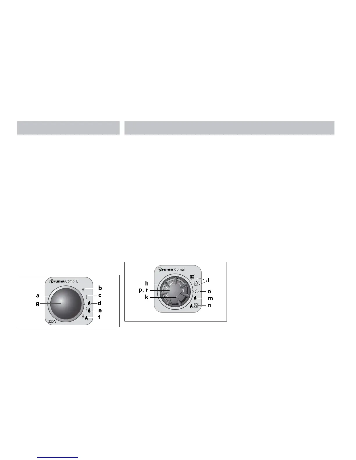
Power selector switch
a = Power selection rotary switch
b = Electric operation 230 V, 1800 W
c = Electric operation 230 V, 900 W
d = Gas operation
e = Mixed operation* (900 W gas and electrical
operation)
f = Mixed operation* (1800 W gas and electrical
operation)
g = Yellow LED on = “Electrical operation”
* Winter mode only!
In summer mode the unit automatically selects
electric operation at the preselected electrical
power of 900 W or 1800 W.
Switching on the electric heating elements
as well does not increase the maximum
heating power.
Control panel
h = Rotary switch for room temperature (1 – 5)
k = green LED lit “Operation” green LED
blinking “after-running” is active in order to
reduce the unit’s temperature
l = Summer operation (water temperature 40 °C
or 60 °C)
m = Winter operation (heating without water
temperature monitoring or with drained
water system)
n = Winter operation (heating with water
temperature monitoring)
o = Rotary “Off” switch
p = yellow LED lit “Boiler heat-up phase”
r = red LED lit, red LED blinking “Failure”
The LEDs are visible only when the unit is
switched on.
Room thermostat
To measure the room temperature, an external
room temperature sensor (s) is located
in the vehicle. The location of the sensor
is determined individually by the vehicle
manufacturer, depending on the vehicle type;
consult the operating instructions for your
vehicle for further details.