CAN – Ethernet Gateway
10 © SYS TEC electronic GmbH 2007 L-1032e_9
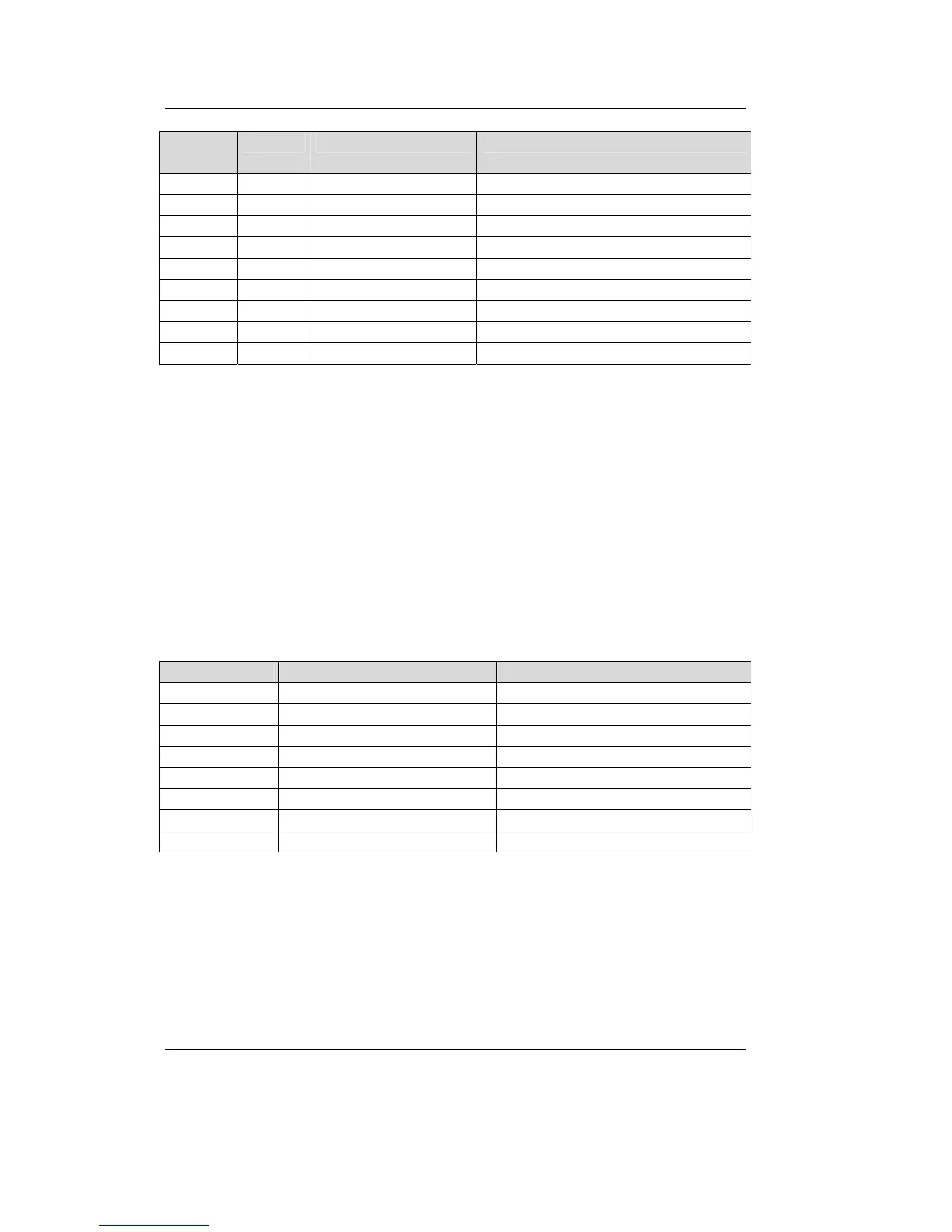
D-Sub-9
Plug
5-pol. Signal Name Description
1 n.c. not connected
2 2 CL (CAN_L) CAN_L bus line
3 1 V- (CAN_GND) CAN Ground
4 n.c. not connected
5 3 SH (CAN_SHLD) CAN Shield
6 GND CAN Ground (optional)
7 4 CH (CAN_H) CAN_H bus line
8 n.c.
9 5 V+ (CAN_V+) not connected
Table 1: CAN Connector Pin Assignment
3.2.2 Ethernet Connection
The Ethernet (10Base-T) signals are routed to an RJ45 socket for easy
connection using a standard CAT 3 or CAT 5 network cable. For
direct connection (without a hub or switch) of a CAN-Ethernet
Gateway and a PC, a crosslink cable is required.
The Ethernet connection is galvanic isolated from the CAN-Ethernet
Gateway
Pin Name Description
1 TX+ Transmit Data +
2 TX- Transmit Data -
3 RX+ Receive Data +
4 n.c. not connected
5 n.c. not connected
6 RX- Receive Data +
7 n.c. not connected
8 n.c. not connected
Table 2: Ethernet Connector Pin Assignment