CAN – Ethernet Gateway
12 © SYS TEC electronic GmbH 2007 L-1032e_9
3.3 Device Status Display
There are a total of 7 LEDs (refer to Table 4) for displaying the
operational state of the device. The displays are arranged according to
their meaning to the networks (refer to
Figure 3). One red and one
green LED show the state of the CAN or Ethernet network. Detailed
description of the "error" LEDs can be found in section
6.1.
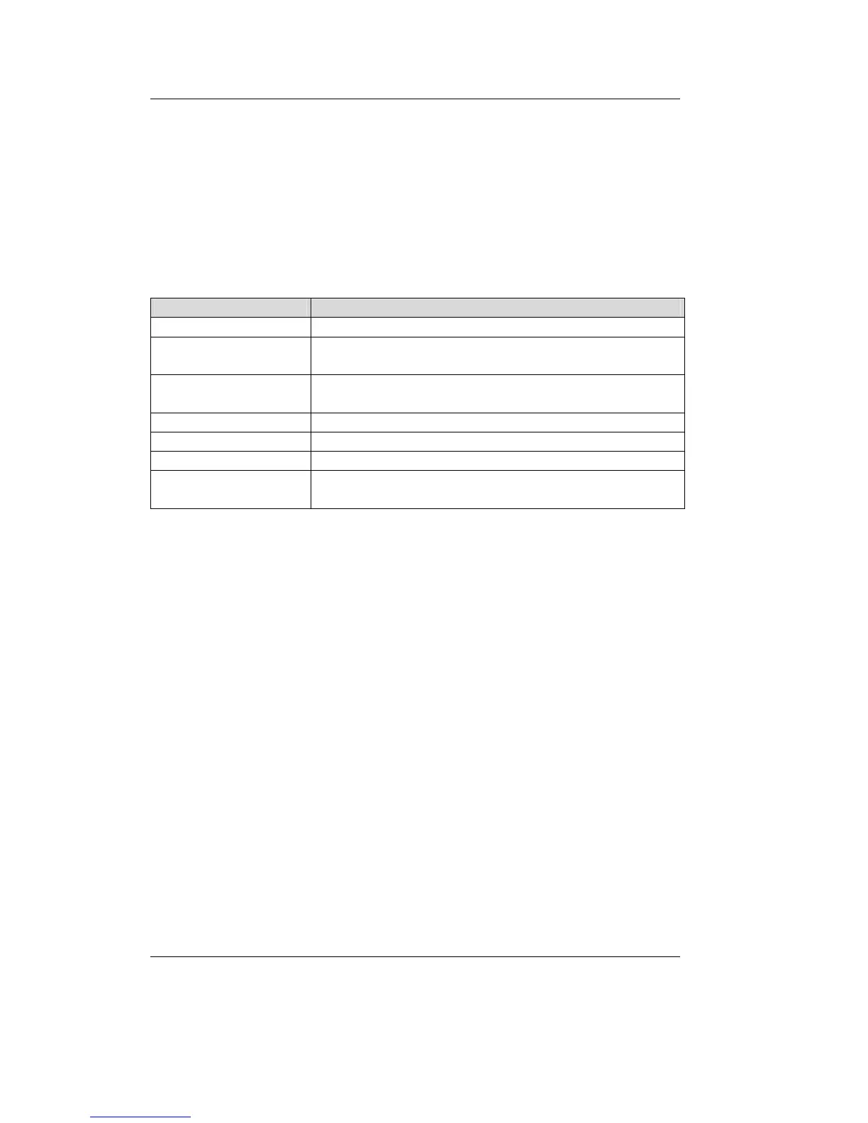
LED Name Description
power Supply Voltage OK [green]
connect A connection to the other Gateway is established over
UDP or TCP [green]
error (Ethernet) Error during data transfer on the Ethernet connection
(refer to section 6.1) [red]
link Connection to Ethernet established, cabling OK [green]
active Data transfer over Ethernet [yellow]
traffic Indicates data traffic on the CAN bus [green]
error (CAN) Error during data transfer on the CAN connection (refer
to section 6.1) [red]
Table 4: Meaning of the Device Status LEDs