CAN – Ethernet Gateway
24 © SYS TEC electronic GmbH 2007 L-1032e_9
4.2 Interfaces
4.2.1 Fundamentals
CAN messages are exchanged over interfaces. An interface establishes
a connection between a CAN message input/output and the central
distributor (data pool in the Gateway module) in the CAN-Ethernet
Gateway. Multiple interfaces can be activated, as long as enough
memory is available on the Gateway.
The two most important interfaces are
can for the CAN interface and
udp or tcp for an Ethernet interface according to the block transfer
protocol.
While the CAN interface sends and receives CAN messages
to and from the CAN network, the UDP interface is responsible for
tunneling the messages over UDP/IP/Ethernet.
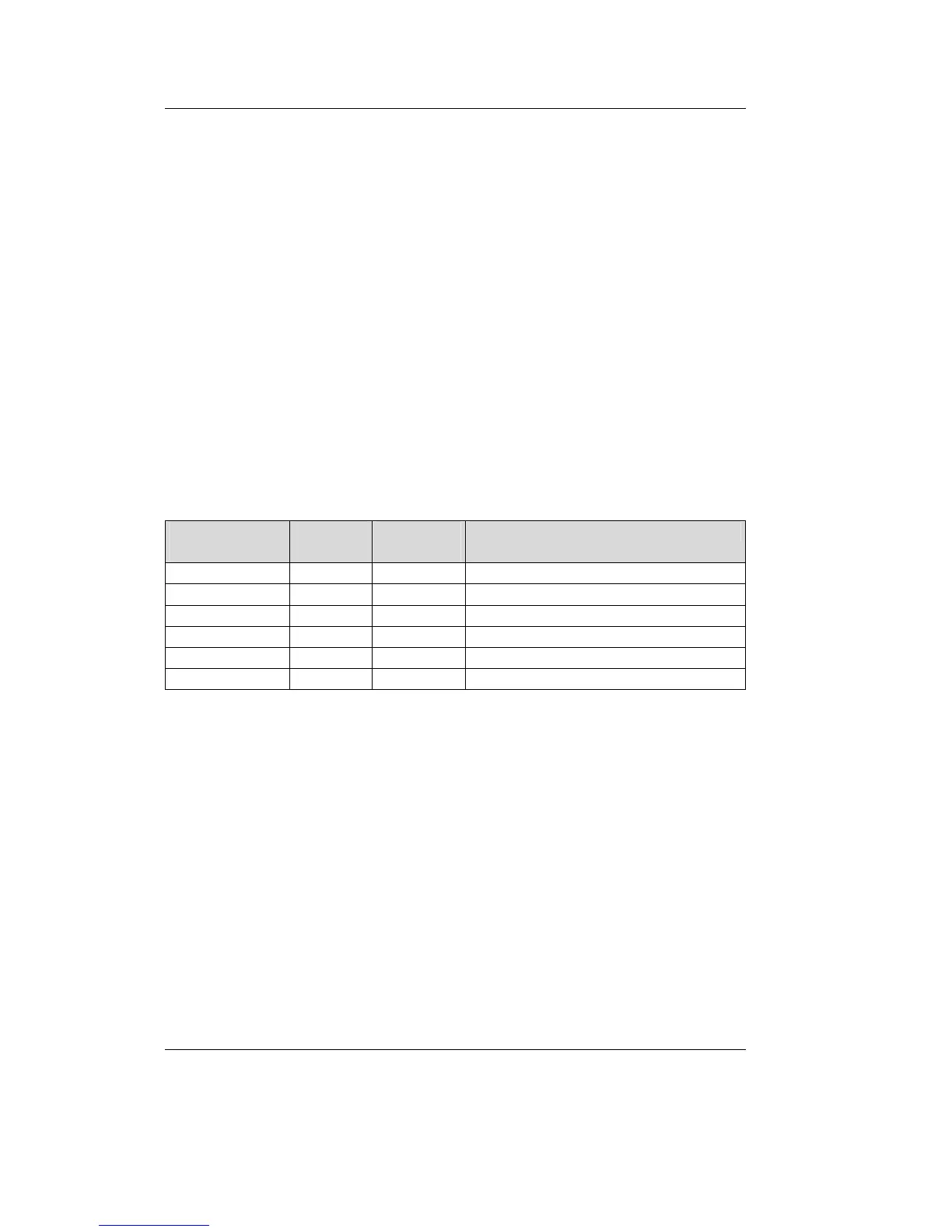
Available
Interfaces
Type Maximum
amount
Requirements
CAN can 1 required, mandatory
UDP Client udp 3 required based on application needs
UDP Server udpserv 1 required, mandatory
TCP Client tcp 3 required based on application needs
TCP Server tcpserv 1 required, mandatory
LED led 1 required, mandatory
Table 6: Interface Overview
The UDP interface transports the CAN messages based on the UDP
protocol while the TCP interface uses TCP as the transport protocol.
Both interface types are functionally identical but vary in terms of
transfer rate.
Interfaces are created with the command
mkif and deleted with the
command
rm. All interfaces that have been created appear in the /if
directory. Within the interface directory there are 3 files. The files
fin
and
fout are responsible for CAN message filtering (refer to section
4.3). The file conf is intended for future expansions and currently
remains unused.