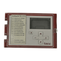
TAC 2112, Manual Functional Description
TAC AB, 1999-08-01 0-004-7459-3 (GB), 7:11(
22
)
Parameters
P No. Parameter Min. Max. Step Default Comments
P 13 Return temperature, heating 0 °C 120 °C 0,3 °C - Step=0,1 at 2–55 °C
P 43 Return limitation on/off 0 2 1 0 (off) 1=heating, 2=heat.+dom.h.w.
P 44 Return limit., heating, P band 10 °C 200 °C 0,5 °C 20 °C Not if P 43=0
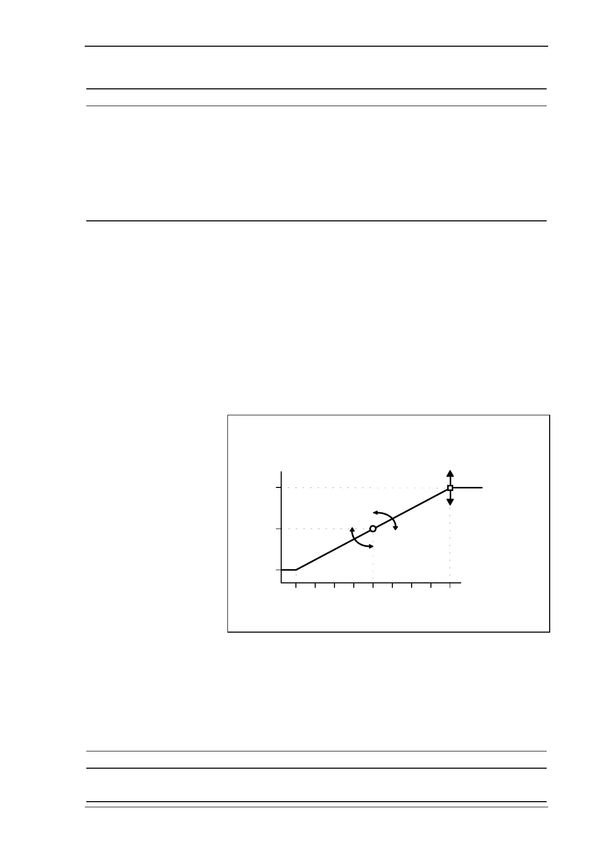
P 45 Curve point x0 -30 °C P 48 1 °C -10 °C Not if P 43=0
P 46 Curve point y0 P 49 120 °C 1 °C 70 °C Not if P 43=0
P 47 Curve point x1 P 46 40 °C 1 °C 10 °C Not if P 43=0
P 48 Curve point y1 10 °C P 47 1 °C 40 °C Not if P 43=0
7.3.8 Remote heating control (SPC)
The heating can be remote-controlled by connecting an external
2–10 V DC control voltage to the SPC input.
In systems with a reference sensor, the setpoint for the room
temperature is affected, and in systems without a reference sensor, the
setpoint for the supply temperature is affected. The effect of the
control voltage on the setpoint is shown in the illustration below.
-40
0
5786910432
+40
E
ect on
setpoint (°C)
SPC signal
(V)
P 81
The effect of the SPC signal on the setpoint
The effect of the control voltage on the setpoint can be adjusted by
means of the
SPC effect at +10 V
parameter (P 81).
When the equipment is delivered, the SPC signal has no effect due to
the fact that the
SPC effect at +10 V
parameter is set to zero.
Parameters
P No. Parameter Min. Max. Step Default Comments
P 80 Current SPC effect (-1)•P 81 P 81 0,1°C -
P 81 SPC effect at +10 V 0 °C 40 °C 1 °C 0 °C