11
English
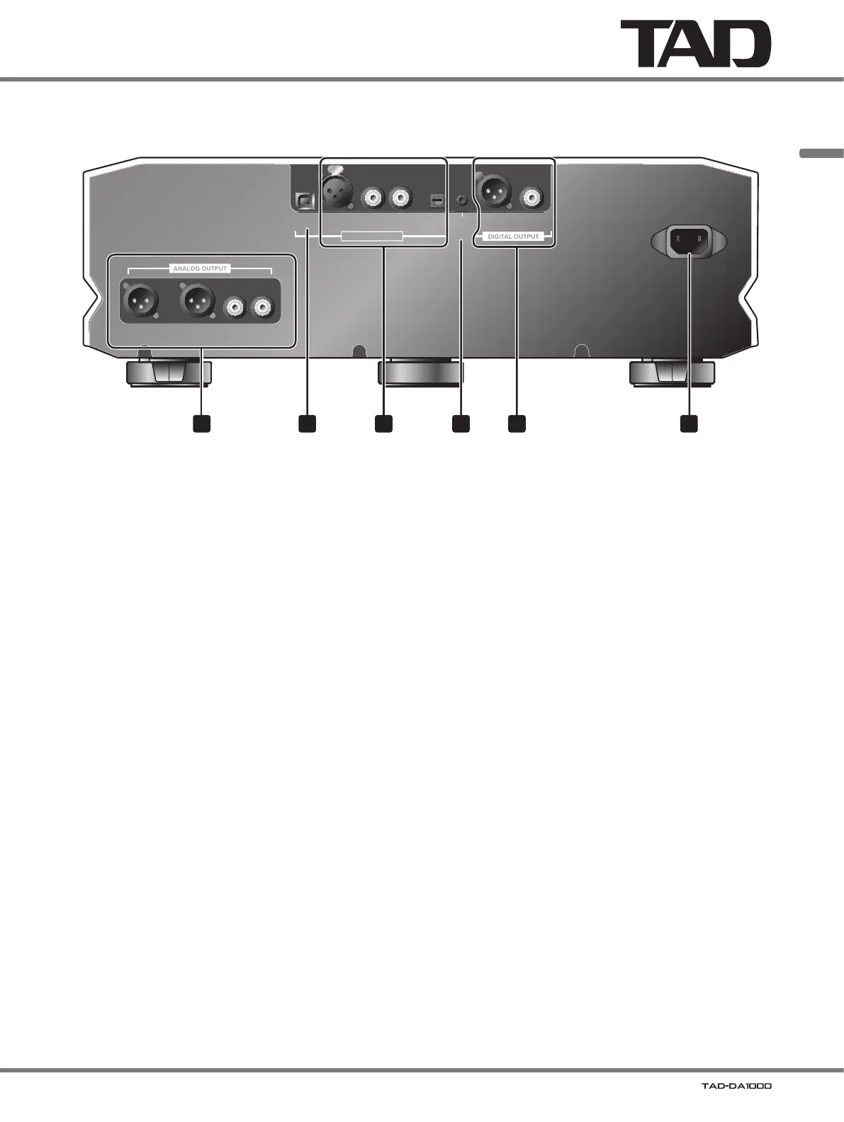
Main unit rear panel
USB XLR COAXIAL OPT
DIGITAL INPUT
XLR COAXIAL
12 V
TRIGGER
IN
D4D1 D2 D3
BALANCED UNBALANCED
LLRR
AC IN
1 52 43 6
1 ANALOG OUTPUT connectors
Connect to Pre-Amplifier.
• BALANCED XLR type
• UNBALANCED RCA type
2 USB port
Use to connect a USB cable to computer.
3 DIGITAL INPUT connectors
Connect to a component equipped with a digital output
connector.
• XLR (balanced) type (D1)
• COAXIAL type (D2, D3)
• OPT (optical) type (D4)
4 12 V TRIGGER IN connector
When this connector is connected to another component
equipped with 12 V trigger, the connected component can
be used to switch this unit’s power ON/standby.
Connector:
Ø 3.5 mm monaural mini-jack
Operating conditions:
• During standby mode, when input signal’s voltage goes
from L to H (power ON mode).
• During power
ON mode, when input signal’s voltage
goes from H to L (standby mode).
When an H signal value is input to the 12 V trigger
connector, the unit’s power switch cannot be used to
switch the unit to the standby mode.
5 DIGITAL OUTPUT connectors
Connect to a component equipped with a digital input
connector.
• XLR (balanced) type
• COAXIAL type
6 AC IN connector
Connect the supplied power cord here.