10 Description TB8100 Installation and Operation Manual
© Tait Electronics Limited June 2005
1.1 The TB8100 BSS Modules
The modules which make up the TB8100 BSS are described briefly below.
You can find more detailed information on these modules in the other
chapters in this manual, and also in the service manual.
Reciter The receiver, exciter and digital
control circuitry is located in the
reciter module. It also incorporates an
optional system interface board which
provides standard system inputs and
outputs.
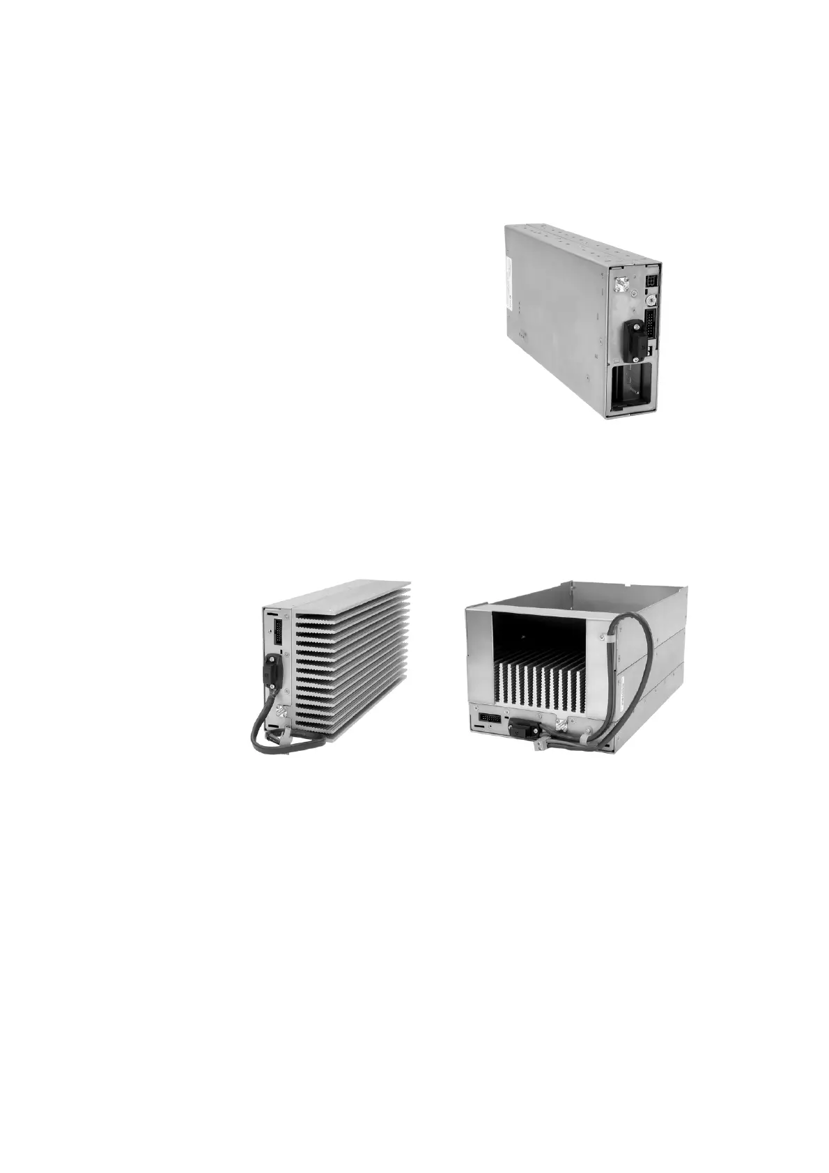
Power Amplifier The power amplifier (PA) amplifies the RF output from the reciter and is
available in 5W, 50W and 100W models.
The 5W and 50W models mount vertically in the subrack, while the 100W
model mounts horizontally as it has a wider heatsink. The 100W PA is also
fitted with an airflow duct.
All three models of PA are designed to operate on the 28VDC output
provided by the TB8100 power management unit. In addition, 5W and
50W models are available for operation on 12VDC. These two 12V PAs
are fitted with an internal boost regulator board, which converts the 12V
nominal DC input to a 28VDC output to power the PA circuit boards. The
boost regulator board also provides a 12VDC output to power the reciter.
5/50W PA 100W PA

 Loading...


