38 Functional Description TB8100 Installation and Operation Manual
© Tait Electronics Limited June 2005
4.1 Base Station System Overview
4.1.1 Single Base Station System
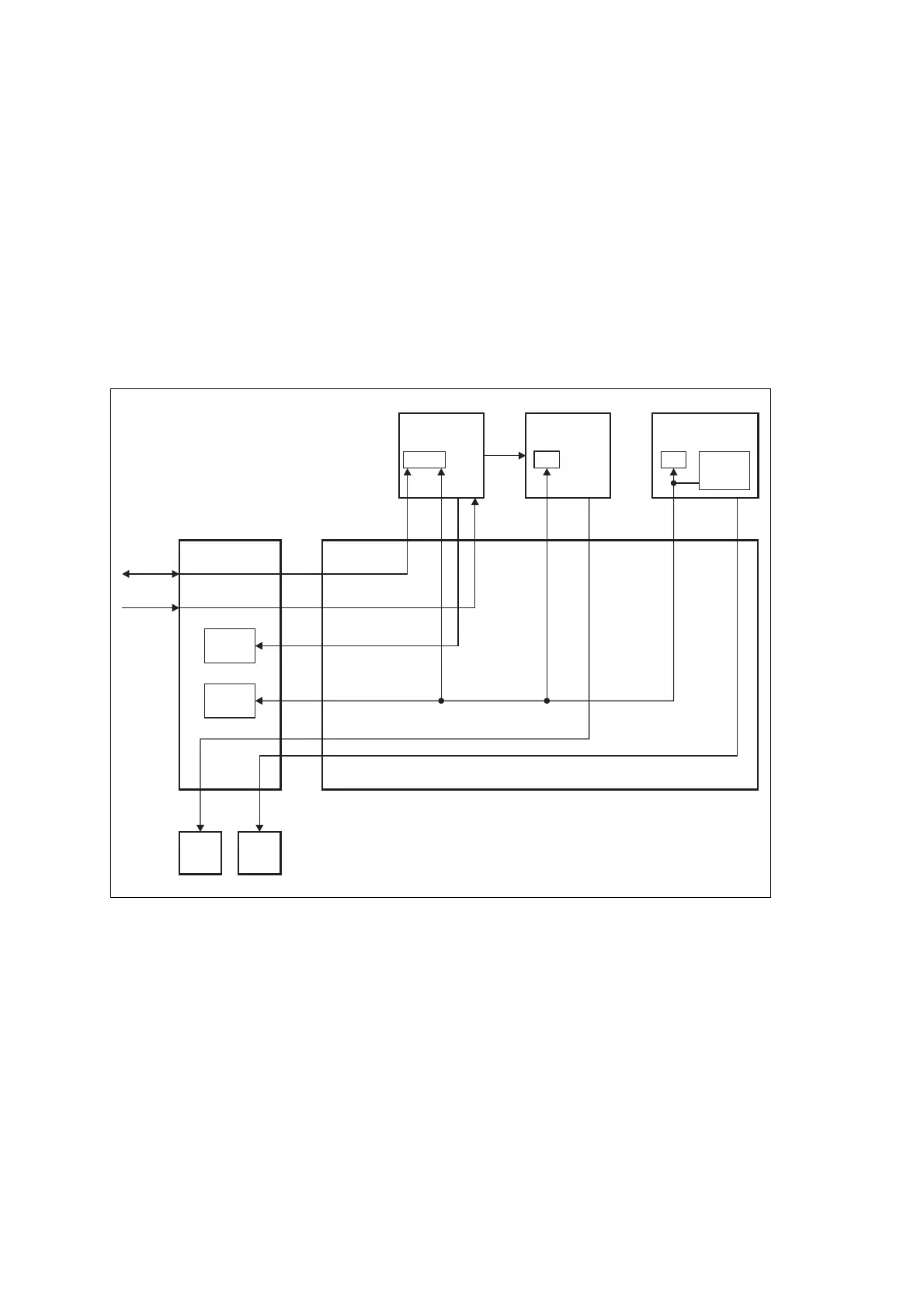
The single base station system comprises a reciter, a PA, and a PMU. The
standard control panel and single base station subrack interconnect board are
used in this type of system. Figure 4.1 below illustrates the main
communication paths. Note that the fans have power supplied from the
relevant module, with the rotation sensor alarm signal interfaced into the
control panel. This signal is processed via the reciter.
4.1.2 Dual Base Station System
In a dual base station system the second base station’s reciter and PA are
isolated from the first base station’s reciter, PA, and PMU. This is achieved
through the use of the dual base station subrack interconnect board and the
dual base station control panel. Solid state relays and control logic on the
interconnect board isolate the two base station communication channels
from each other. All other signals remain in parallel. The relays are
controlled by a key press of the base station select buttons on the control
panel.
Figure 4.1 Single base station system communication paths
Microphone
Fan
I C
2
I C
2
I C
2
I C
2
RS-232
Mic
Speaker
Fan
RS-232
PA
µP
Subrack Interconnect Board
Reciter
µP
Control Panel
PMU
Fan
PA
Fan
User
Controls
Speaker
PMU
µP
I C Current
Source
2

 Loading...


