TB8100 Installation and Operation Manual Circuit Description 23
© Tait Electronics Limited June 2005
The leaded high-power components are situated on the DC converter
board, while the plug-in cards have only SMD control components.
Standby Power
Supply
This optional power supply card plugs into the DC converter board and
provides power to the reciter output. This allows the main DC unit to be
switched off to reduce current consumption in low-power situations, e.g.
when the PA is not transmitting. Also, when battery capacity is low, it will
maintain the power supply to the microprocessor and shut down the rest of
the PMU. This card must be fitted to enable the software-controlled power
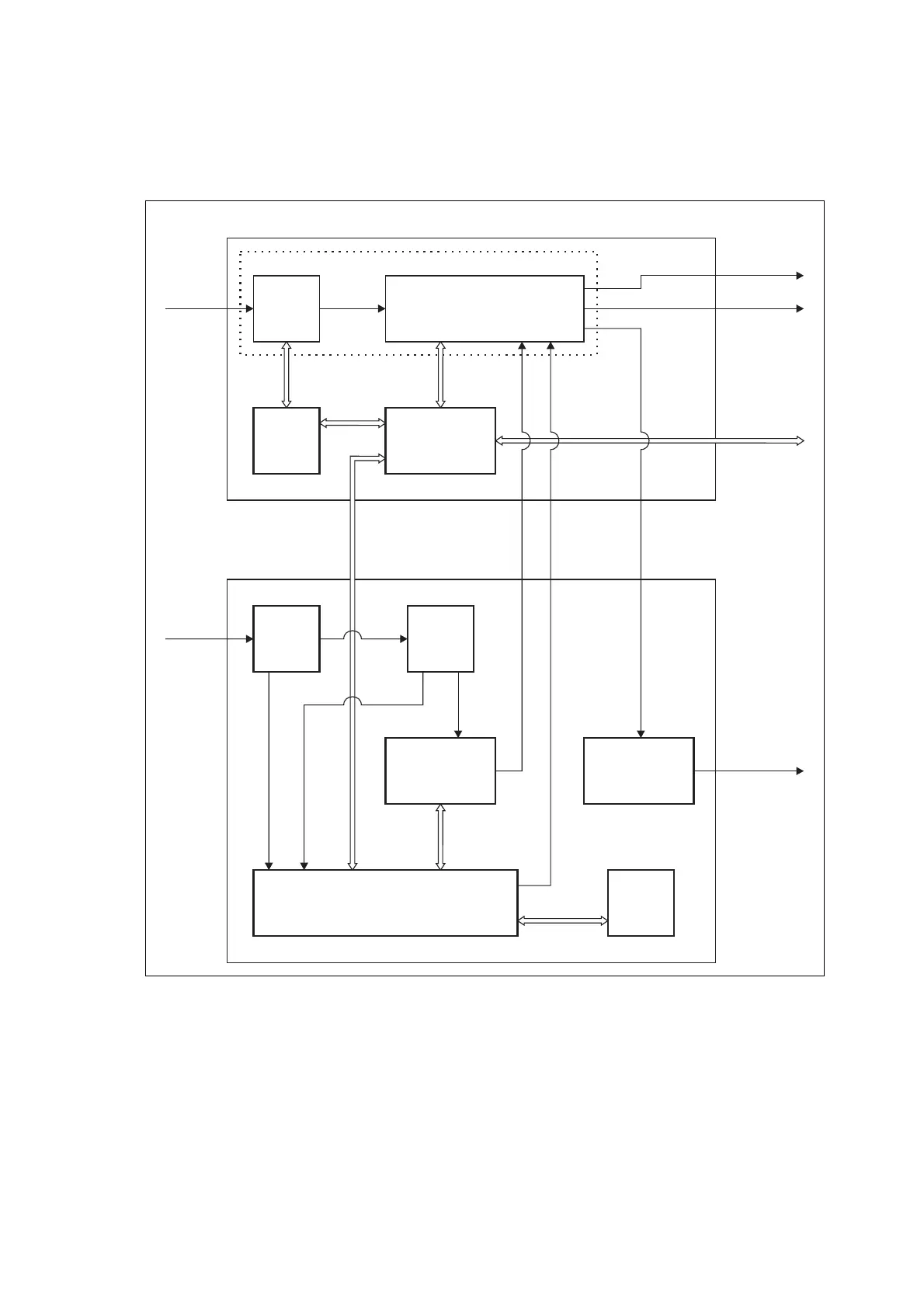
Figure 2.4 PMU high level block diagram
PFC
Circuitry
PFC
Control
Card
DC Input
Filter
Card
DC
Control
Card
Auxiliary
Power Supply
Board*
Battery
Control
Card
Standby
Power Supply
Card*
HVDC Control &
Microprocessor
Card
HVDC Circuitry
DC Converter Board
28V
28V
28V O/P (PA)
System
Control Bus
28V O/P (Reciter)
AC I/P
115/230V
50/60Hz
400VDC
DC I/P
12/24/48V
28V
DC O/P
13.65/27.3/54.6V
*optional
AC Converter Board
AC Module
DC Module

 Loading...


