4–27
Chapter 4: Removing and Replacing Components
Procedure 14: Lower Tractor Removal
Step 1. Remove the Ribbon Platform (see Procedure 1).
Step 2. Tilt the Print Mechanism (see Procedure 10).
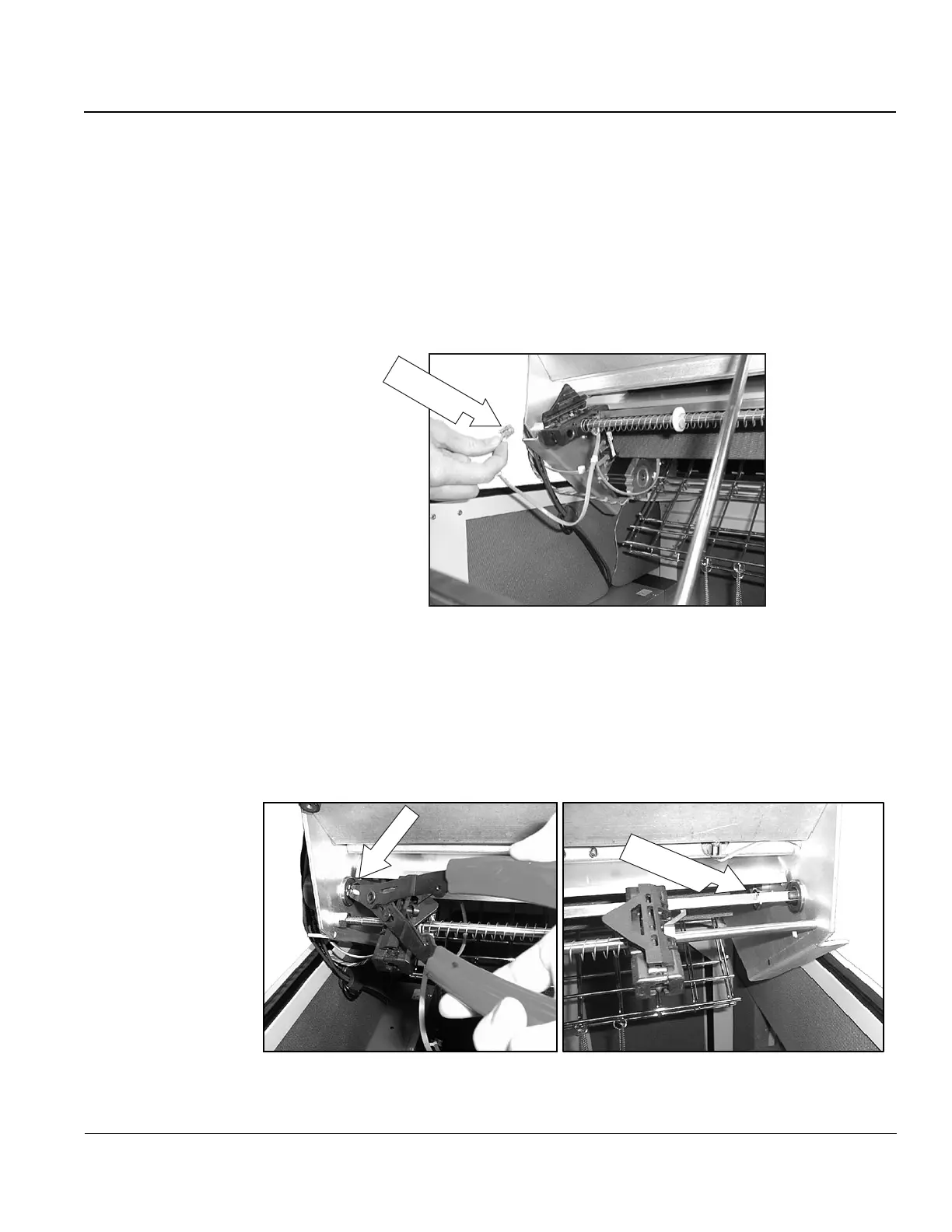
Step 3. Unplug the Paper Out sensor cable from J1 of the Platen/Paper Sensor PCA.
(The Paper Out Sensor is part of the Lower Left Tractor Assembly).
Paper Out
Sensor Cable
Figure 29. Location of Paper Out sensor cables.
Step 4. Remove the retaining (snap) rings from both ends of the squared shaft (located
inside the frame at each end). Leave the rings sitting loosely on the shaft.
Snap Ring
Snap Ring
After Removal
Figure 30. Removing Retaining (Snap) rings.