39
83503001 Rev G
3.9.2. Current Carrying Capacity
Two factors must be considered when selecting the wire size:
a) Wires should be at least heavy enough not to overheat while carrying the power
supply load current at the rated load, or the current that would flow in the event the
load wires were shorted, whichever is greater.
b) Wire size should be selected to enable voltage drop per lead to be less than 1.0V at
the rated current. Although units will compensate for up to 5V in each load wire, it is
recommended to minimize the voltage drop (1V typical maximum) to prevent
excessive output power consumption from the power supply and poor dynamic
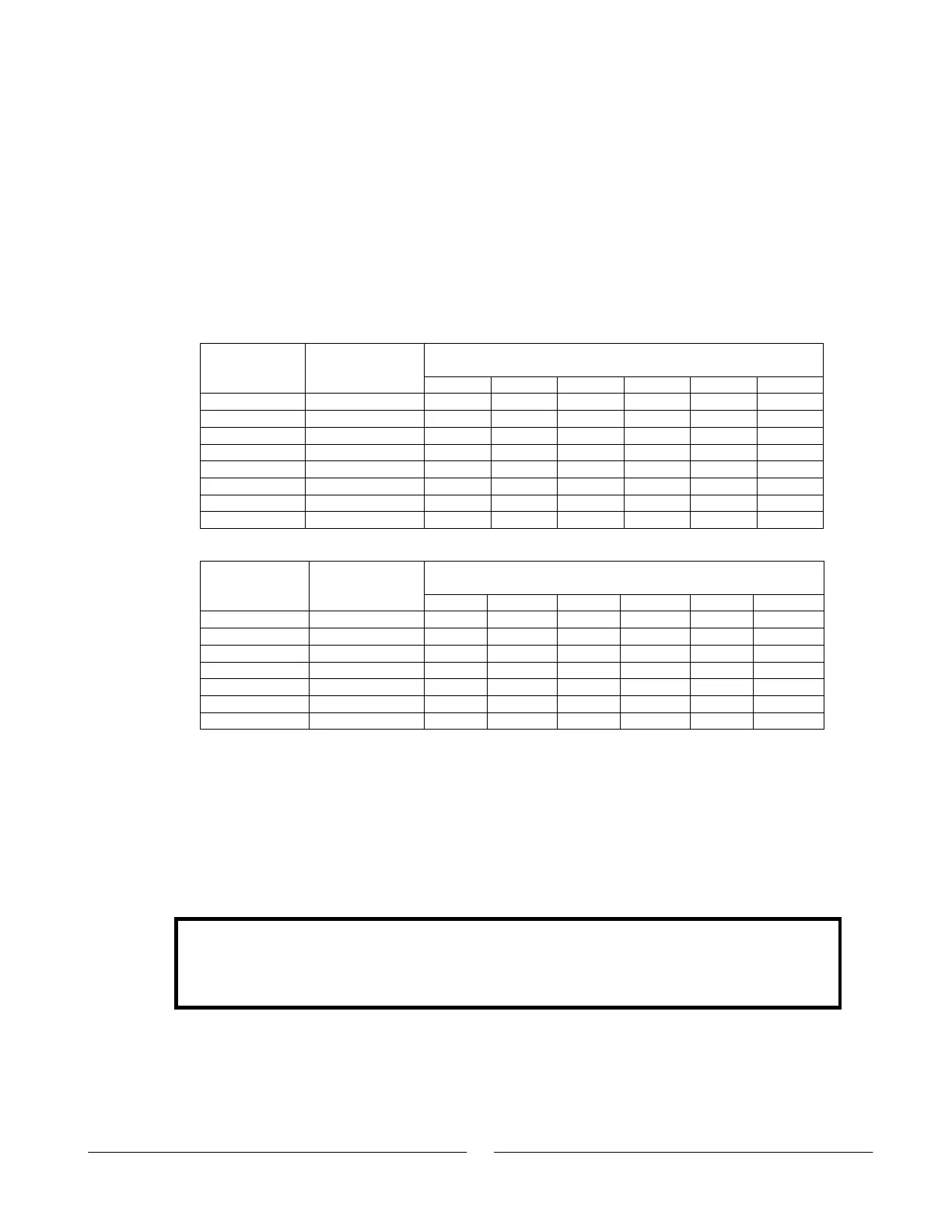
response to load changes. Please refer to Tables 3-2 and 3-3 for maximum wire
length (to limit voltage drop) in American and European dimensions respectively.
Maximum length in Feet to limit
voltage drop to 1V or less
Wire size
AWG
Resistivity
OHM/1000ft
10A 20A 50A 100A 200A 400A
14 2.526 40 20 8 4 2 ---
12 1.589 60 30 12 6 3 ---
10 0.9994 100 50 20 10 5 2
8 0.6285 160 80 32 15 8 4
6 0.3953 250 125 50 25 12 6
4 0.2486 400 200 80 40 20 10
2 0.1564 600 300 125 60 30 15
0 0.0983 1000 500 200 100 50 25
Table 3-2: Maximum wire length for 1V drop on lead (in feet)
Maximum length in meters to limit
voltage drop to 1V or less
Cross sect.
area
(mm²)
Resistivity
OHM/Km
10A 20A 50A 100A 200A 400A
2.5 8.21 12.0 6.0 2.4 1.2 0.6 0.3
4 5.09 18.6 9.8 4.0 2 1.0 0.5
6 3.39 29.4 14.8 5.8 2.9 1.45 0.7
10 1.95 51.2 25.6 10.2 5.1 2.5 1.25
16 1.24 80.0 40.0 16.0 8 4 2
25 0.795 125.0 62.0 25.2 12.6 6.3 3.1
35 0.565 177.0 88.0 35.4 17.7 8.8 4.4
Table 3-3: Maximum Wire Length for 1 V Drop on Lead (in meters)
For currents not shown in Table 3-2 and 3-3, use the formula:
Maximum length=1000/(current x resistivity)
Where current is expressed in Amperes and resistivity in ohms/km or ohms/1000ft.
3.9.3. Wire Termination
The wires should be properly terminated with terminals securely attached. DO NOT use
unterminated wires for load connection at the power supply.
CAUTION
When local sensing, a short from +LS or +S to -V or -S or -LS, will cause damage to
the power supply. Reversing the sense wires might cause damage to the power
supply in local and remote sensing. (Do not connect -S to +V or +S to -V).