71
83503001 Rev G
6.6. Remote Monitoring of Output Voltage and Current
The J1 connector, located on the rear panel provides analog signals for monitoring the
Output Voltage and Output Current. Selection of the voltage range between 0-5V or 0-10V
is made by setup switch SW1-4. The monitoring signals represent 0 to 100% of the power
supply Output Voltage and Output Current. The monitor outputs have 500 ohm series
output resistance. Ensure that the sensing circuit has an input resistance of greater than
500 Kohm or accuracy will be reduced.
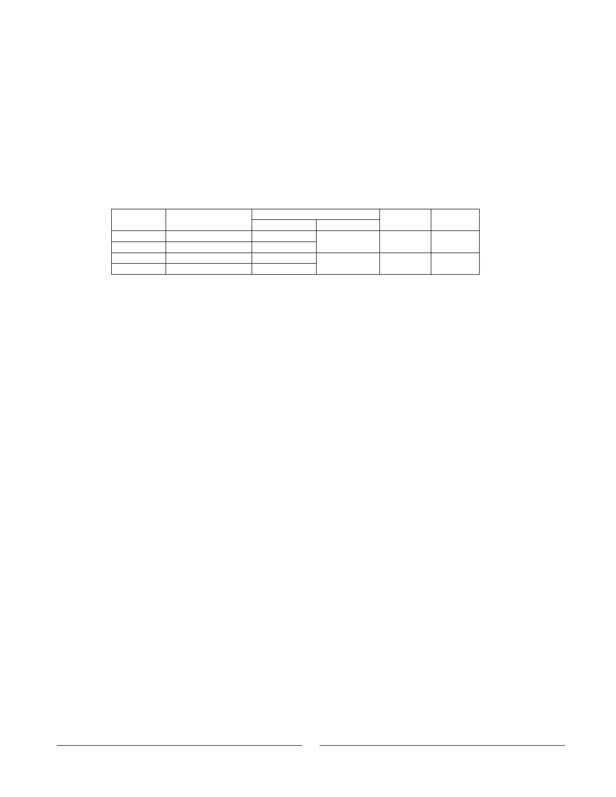
Refer to Table 6-5 for the required J1 connection, SW1-4 setting and monitoring voltage
range.
J1 connectionSignal
name
Signal function
Signal (+) Return (-)
Range SW1-4
VMON V
out
monitor J1-11
IMON I
out
monitor J1-24
J1-12 0-5V Down
VMON V
out
monitor J1-11
IMON I
out
monitor J1-24
J1-12 0-10V Up
Table 6-5 Monitoring signals setting
Notes:
1. Radiated emissions, FCC
requirements:
FCC requirements for radiated emissions; use
shielded cable for the analog control signals; if
using unshielded cable, attach an EMI ferrite
suppressor to the cable, as close as possible to the
power supply.
2. Front panel encoders
operation:
In remote analog mode, the output voltage and
current can’t be set by the voltage and current
encoders.
3. Front panel PREV button: Use the PREV button to display the Output Voltage
and Current setting defined by the encoders or
communication.
4. Communication: In Remote analog mode, all power supply
parameters can be programmed and readback via
the communication port, except the output voltage
and current setting.