49
83503001 Rev G
Table 4-1: Front Panel Controls and Indicators (continued)
Number Control/Indicator Description Section
15 PREV indicator
Green LED, lights when PREV button is pressed
16 FINE button
Main function: Voltage and Current Fine/Coarse adjustment control.
Operates as a toggle switch. In Fine mode, the VOLTAGE and
CURRENT encoders operate with high resolution and in Coarse
mode with lower resolution (approx. 6 turns).
Auxiliary function: Advanced Parallel Operation Mode setting.
5.15.2
17 FINE indicator
Green LED, lights when the unit is in Fine mode.
18 ALARM indicator
Red LED, blinks in case of fault detection. OVP, OTP Foldback,
Enable and AC fail detection will cause the ALARM LED to blink.
19 AC Power switch
AC On/Off control.
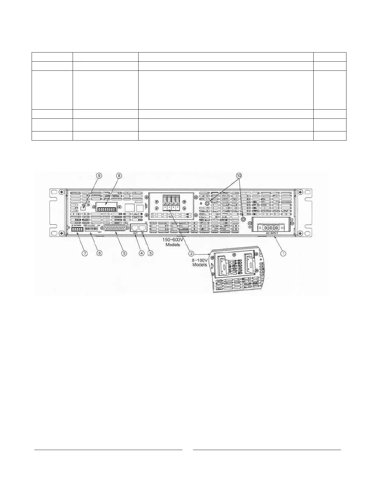
4.3. Rear Panel Connections and Controls
See Fig.4-2 to review the connections and controls located on the power supply rear panel.
Refer to Table 4-2 for explanations about the rear panel connections and controls.
Fig. 4-2: Rear Panel Connections and Controls