28
83503001 Rev G
2. SPECIFICATIONS
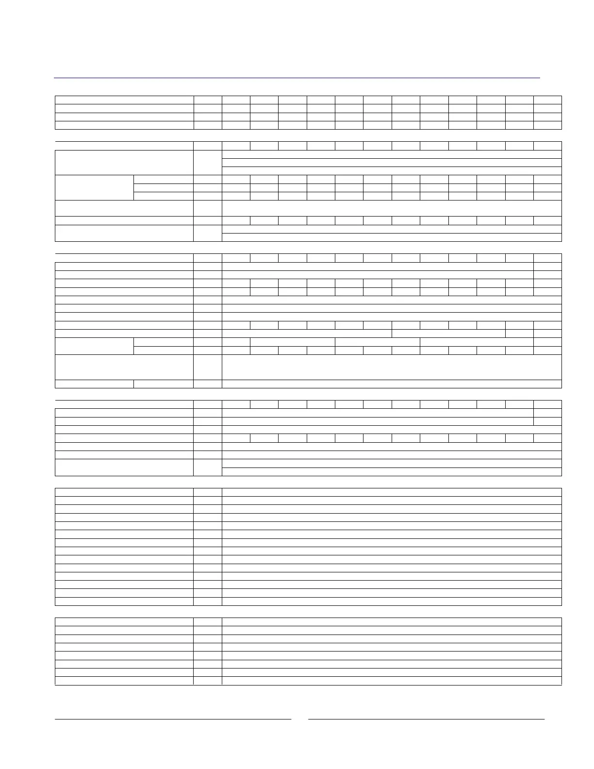
2.1. OUTPUT RATING
GEN 8-400 10-330 15-220 20-165 30-110 40-85 60-55 80-42 100-33 150-22 300-11 600-5.5
(*1) V 8 10 15 20 30 40 60 80 100 150 300 600
utput Current (*2) A 400 330 220 165 110 85 55 42 33 22 11 5.5
utput Power W 3200 3300 3300 3300 3300 3400 3300 3360 3300 3300 3300 3300
2.2. INPUT CHARACTERISTICS
V 8 10 15 20 30 40 60 80 100 150 300 600
-265V, 47~63Hz.
-Phase, 200V models: 170~265V, 47~63Hz.
1. Input voltage/freq. (*3)
---
-Phase, 400V models: 342~460V, 47~63Hz.
Single phase A 24.0 24.0 24.0 24.0 23.0 24.0 23.0 23.5 23.0 23.0 23.0 23.0
3~Phase, 200V A 14.5 14.5 14.5 14.5 14.0 14.5 13.6 14.0 13.7 13.7 13.8 13.9
Maximum input
current at 100% load
3~Phase, 400V A 7.2 7.2 7.2 7.2 7.0 7.2 6.8 7.0 6.8 6.8 6.9 7.0
---
models: 0.99@200Vac, rated output power. 3-Phase models: 0.95@200/380Vac, rated output
.
% 82 83 83 83 86 86 88 88 88 87 87 87
-Phase 200V models: Less than 50A
--
-Phase 400V models: Less than 20A
2.3. CONSTANT VOLTAGE MODE
V 8 10 15 20 30 40 60 80 100 150 300 600
Max. line regulation (*6) --- 0.01% of rate output voltage +2mV
2. Max. load regulation (*7)
--- 0.015% of rated output voltage +5mV
-p (20MHz) (*8) mV 60 60 60 60 60 60 60 80 100 100 300 500
~1MHz mV 8 8 8 8 8 8 8 25 25 25 100 120
PPM/°C
PPM/°C @ Rated Current, following 30 minute warm up
Temperature Stability ---
for 8hrs after 30 min warm-up. Constant line, load & temp.
---
Less than 0.05% of rated output voltage+2mV over 30 minutes followi
ng power on.
8. Rem. Sense compensation/wire
V 2 2 2 2 5 5 5 5 5 5 5 5
9. Up prog. Response time, 0
~Vomax.(*9) mS 80 150 200 250
mS 20 100 160 300 500
-prog.
response time
No load (*10) mS 500 600 700 800 900 1000 1100 1200 1500 2000 3900 4000
11. Transient response time
mS
Time for output voltage to recover within 0.5% of its rated output for a load change 10
-90% of rated output
-point: 10-100%, Local sense.
Less than 1mS, for models up to and including 100V. 2mS, for models above 100V.
-up time (Typ) mS
-Phase and 3-Phase 200V models, 6mSec for 3-Phase 400V models. Rated output power.
2.4. CONSTANT CURRENT MODE
V 8 10 15 20 30 40 60 80 100 150 300 600
Max. line regulation (*6) --- 0.01% of rate output current +2mA
2. Max. load regulation (*11)
--- 0.02% of rated output current +5mA
3. Load regulation thermal drift
---
Less than 0.1% of the rated output current over 30 minutes
following load change
~1MHz (*12) mA 1300 1200 880 660 300 200 100 80 70 60 20 10
PPM/°C
00 PPM/°C from rated output voltage, following 30 minutes warm-up
Temperature Stability ---
d I
for 8hrs after 30 min warm-up. Constant line, load & temp.
---
-20V model: Less than +/-0.5% of rated output current over 30 minutes following power on.
-600V model: Less than +/-0.25% of rated output current over 30 minutes following power on.
2.5. ANALOG PROGRAMMING AND MONITORING
V
voltage programming ---
~100%, 0~5V or 0~10V, user selectable. Accuracy and linearity. +/-0.5% of rated V
.
voltage programming (*13) ---
~100%, 0~5V or 0~10V, user selectable. Accuracy and linearity. +/-1% of rated V
.
resistor programming ---
~100%, 0~5V/10Kohm full scale, user selectable, accuracy and linearity. +/-1% of rated V
.
resistor programming (*13) ---
~100%, 0~5V/10Kohm full scale, user selectable, accuracy and linearity. +/-1% of rated V
.
---
~0.6V/2~15V, or dry contact (Open/Short) user selectable logic.
6. Output current monitor (*
13) ---
~5V or 0~10V, accuracy: +/-1%, user selectable
. Output voltage monitor ---
~5V or 0~10V, accuracy: +/-1%, user selectable
8. Power supply OK signal
---
-OK, 0V-Fail. 500ohm series resistance
---
Possible, up to 4 identical units in master/slave mode with two wire current balance connection
0. Series operation ---
Possible, up to 2 identical units (with external diodes).
indicator ---
Open collector. CC mode: On, CV mode. Off. Maximum voltage: 30V, maximum sink current: 10mA
---
Open: Off, Short: On; Dry Contact
. Max Voltage @ Enable/Disable In = 6V.
13. Local/Remote mode Control
---
electrical signal or dry contact (Open/Short), 0~0.6V or short-Remote, 2~15V or open-Local
14. Local/Remote mode Indicator
---
Open collector. Local: open, Remote: ON. Maxi
mum: 30V, maximum sink current 10mA.
2.6. PROGRAMMING AND READBACK (RS232/485, Optional IEEE Interface)
V
out
programming accuracy ---
of actual output voltage +0.05% of the rated output voltage
out
programming accuracy (*13) ---
current +0.2% of rated output current
out
programming resolution ---
out
programming resolution ---
out
readback accuracy ---
0.1% of actual output voltage +
0.1% of rated output voltage
I
out
readback accuracy (*13) ---
0.1% of actual output voltage +0.3% of rated output current
out
readback resolution ---
out
readback resolution