42
83503001 Rev G
The 150V to 600V models have a four terminal wire clamp output connector:
Phoenix Contact P/N: FRONT4-H-7.62/4
The two left terminals are the positive outputs and the two right terminals are the
negative outputs. Max. 30A per terminal.
The connector requirements are as follows:
a) Wires: AWG18 to AWG10.
b) Tightening torque: 4.4-5.3 Lb-inch. (0.5-0.6Nm).
Follow the below instructions for connection of the load wires to the power supply:
a) Strip approx. 10mm at the end of each of the load wires.
b) Loosen the connector terminal screws.
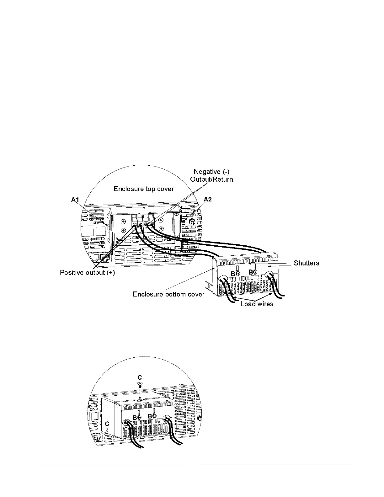
c) Loosen screws “B” from enclosure bottom cover to release the shutter.
d) Insert stripped wires into enclosure bottom cover opening and then to the terminals,
tighten the terminals screws securely (see fig. 3-9)
e) Assemble the enclosure top cover to the chassis as shown in Fig. 3-9, using clamp
“A1” and screw “A2”, tighten screw “A2” (tightening torque: 4.8-5.3 Lb-inch).
Fig. 3-9: Load Wires Connection to the Output Connector
f) Assemble the enclosure bottom cover to its place, as shown in Fig. 3-10, using
screws “C”, 3 places (tightening torque 4.8-5.3 Lb inch).
g) Slide down the shutter to secure load wires in place, and tighten screws “B”.
Fig. 3-10: Enclosure assembly