53
83503001 Rev G
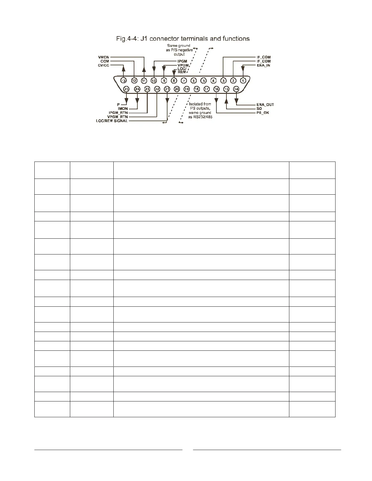
Table 4-4: J1 Connector Terminals and Functions
J1
contact Signal name Function Reference
J1-1 ENA_IN Enable/Disable the power supply output by dry-contact (short/open)
with ENA_OUT.
Sec. 5.8
J1-2
J1-3
IF_COM Isolated Interface Common. Return for the SO control, PS_OK signal
and for the RS232/485 and IEEE interfaces.
Sec. 5.7, 5.10
J1-47 N/C No Connection
J1-8 LOCAL/
REMOTE
Input for selecting between Local or Remote analog programming of
Output Voltage and Output Current.
Sec. 6.2
J1-9 VPGM Input for remote analog voltage/resistance programming of the
Output Voltage.
Sec. 6.1~6.4
J1-10 IPGM Input for remote analog voltage/resistance programming of the
Output Current.
Sec. 6.1~6.4
J1-11 VMON Output for monitoring the power supply Output Voltage. Sec. 6.6
J1-12 COM Control Common. Return for VMON, IMON, CV/CC, LOC/REM.
Referenced internally to the negative sense potential.
J1-13 CV/CC Output for Constant-Voltage/Constant-Current mode indication. Sec. 5.9
J1-14 ENA_OUT Enable/Disable the power supply output by dry-contact (short/open)
with ENA_IN.
Sec. 5.8
J1-15 SO Input for Shut-Off control of the power supply output. Sec. 5.7
J1-16 PS_OK Output for indication of the power supply status. Sec. 5.10
J1-1720 N/C No Connection.
J1-21 LOC/REM
SIGNAL
Output for indicating if the unit is in Local or Remote analog
programming mode.
Sec. 6.3
J1-22 VPGM_RTN Return for VPGM input. Connected internally to J1-12 terminal. Sec. 6.1~6.5
J1-23 IPGM_RTN Return for IPGM input. Referenced internally to the negative output
potential.
Sec. 6.1~6.5
J1-24 IMON Output for monitoring the power supply Output Current. Sec. 6.6
J1-25 P Output for current balance in parallel operation. Connected internally
to J1-24 terminal.
Sec. 5.15