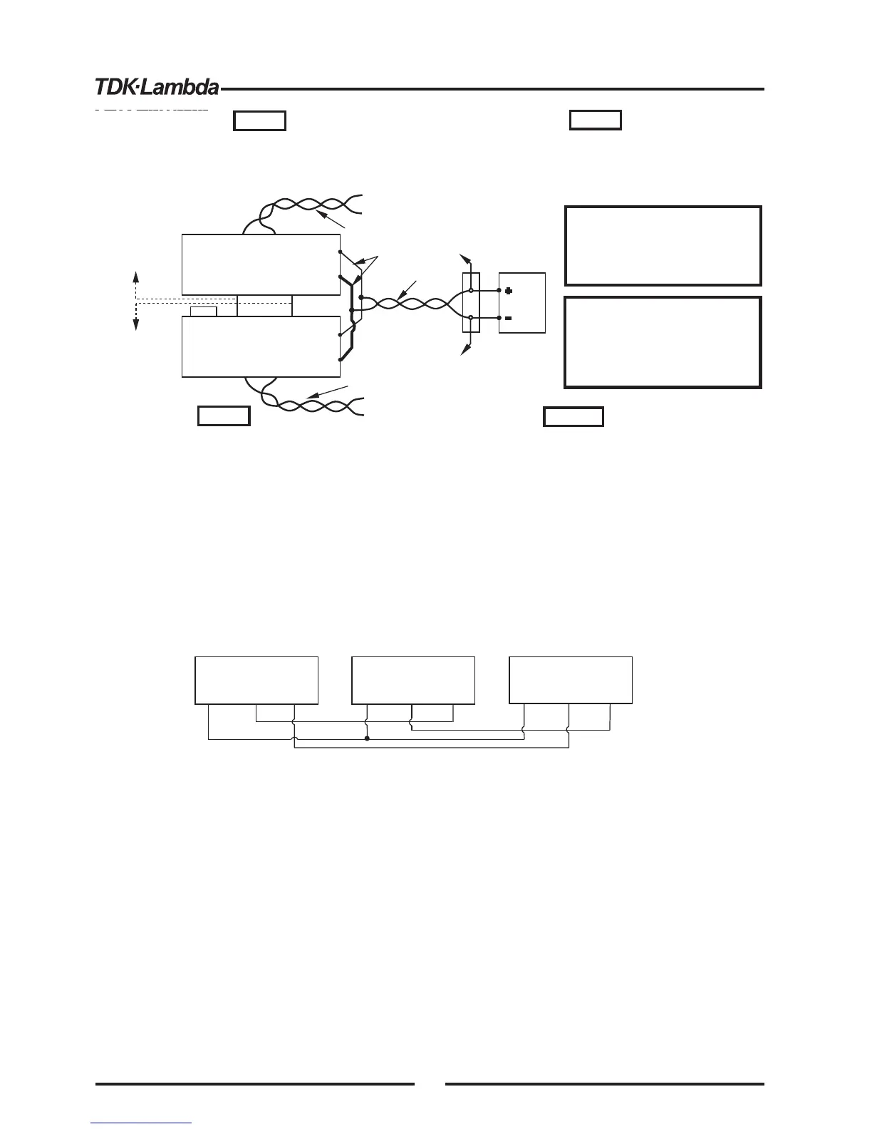
Fig.5-5: Parallel operation
wiith Remote sensing
With local sensing it is important to minimize the wire
length and resistance. Also the positive and negative
wire resistance should be close as possible to each
other to achieve current balance between power
supplies.
5.16 DAISY-CHAIN CONNECTION
It is possible to configure amultiple power supply system to shut down all the unitswhen a fault
condition occurs in one of the units. When the fault is removed, the system recovers according to its
setting to Safe start mode orAutomatic restart.
Setup switch SW1 position 5 should be set to itsDown position to enable the Daisy-chain operation.
Other SW1 positions can be set according to the application requirements.
Ifafault occurs in one of the unitsits PS_OK signal will be set to low level and the display will indicate
the fault. The other unitswill shut off and their display will indicate "SO”. When the fault condition is
removed, the unitswill recover to their last setting according to their Safe start orAuto-restart setting.
Fig.5-6 shows connection of three units, however the same connection method applies to systems
with a larger number of units.
Fig.5-6: Daisy-chain connection
POWER SUPPLY
#
1
J1-2,3
J1-16
J1-16
J1-16
J1-15
PS_OK
POWER SUPPLY
#
2
J1-2,3
J1-15
PS_OK
SO
POWER SUPPLY
#3
J1-2,3
J1-15
PS_OK
SO
SO
IF_COM
IF_COM
IF_COM
5.17 FRONT PANELLOCKING
The front panel controls can be locked to protect from accidental power supply parameter change.
Press and hold PREV button to toggle between “Locked front panel” and “Unlocked front panel”.
The display will cycle between “LFP” and “UFP”. Releasing the PREV button while one of the
modes is displayed, selects that mode.
In this mode, the front panel controls are enable to program and monitor the power supply
parameters.
In this mode the following front panel controls are disabled:
- VOLTAGE and CURRENT encoders.
- FOLD button.
- OUT button.
The power supply will not respond to attemptsto use these controls. The VOLT display will show
“LFP” to indicate that the front panel is locked.
OVP/UVLbutton is active to preview the OVP and UVL setting.
Use PREV button to preview the output voltage and current setting or to unlock the front panel.
5.17.1 Unlocked front panel
5.17.2 Locked front panel
MASTER
POWER SUPPLY
SLAVE#1
POWER SUPPLY
J1-25
J1-10
P
IPGM
J1-12 COM
J1-23
IPGM_RTN
Twisted
pair
+V
-V
+
V
-V
+S
-S
+
-
LOAD
As shortas possible
Twisted
pair
+S-S
+S
-S
Twisted
pair
+S-S
+S
-S
J1-8
J1-12
To J1-10
SLAVE#2
POWER SUPPLY
To J1-23
SLAVE#2
POWER SUPPLY
Make sure that the connection
between -Vo terminals is reliable to
avoid disconnection during operation.
Disconnection may cause damage to
the power supply.
1.In parallel operation, the AC Supply should be applied
to the Master Unit first and then to the Slave unit.
2.The above sequence is not required if the units are
connected in daisy-chain.
CAUTION
VORSICHT
HINWEIS
HINWEISE
NOTE
NOTES
Bei lokalem Sensing ist es wichtig, Länge und
Widerstand der Ausgangsleitungen möglichst gering zu
halten. Zudem sollten die Leitungswiderstände der Plus-
und Minus- Leitungen möglichst identisch sein, um eine
gleichmä ige Lastaufteilung unter den Netzteilen zu
erreichen.
ß
Stellen Sie sicher, dass die
Verbindung zwischen den -V
Anchlussklemmen sich nicht
während des Betriebs lösen kann.
Eine Unterbrechung kann die
Netzteile beschädigen.
1. Bei Parallelbetrieb sollte zunächst das Master-Netzteil mit dem Netz
verbunden werden, danach das Slave-Netzteil.
2. Bei "Daisy-chain" -Betrieb ist diese Abfolge nicht erforderlich.
44