64
8.3ISOLATED PROGRAMMING&MONITORING CONNECTOR
RefertoTable 8-1 for detailed description of therearpanel Isolated Programming&Monitoring
connector. To provide the lowestnoise performance,itis recommended to useshielded-twisted
pair wiring.
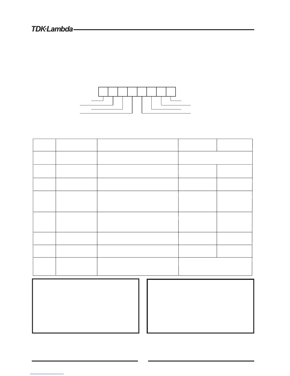
RefertoFig.8-1 fordescriptionofthe connector.
1
2
3
4
5
6
7
8
Shield
+VPROG_ISO
+IPROG_ISO
GND
Shield
+IMON_ISO
+VMON_ISO
GND
+VPROG_ISO
Terminal
Signal name
Function
Shield, connected internally to
chassisofthe supply.
0-5/0-10V
0-5/0-10V
0-5/0-10V
0-5/0-10V
4-20mA
4-20mA
4-20mA
4-20mA
Range 0-5/0-10V
IS510 option
Range 4-20mA
IS420 option
Chassisground
Chassis ground
SHLD
1
Output voltage programming input
Output current programming input
2
+IPROG_ISO
3
Ground for programming
signals.
Ground for programming
signals.
Output voltage monitoring output
Output current monitoring output
Shield, connected internally to
chassisofthe supply.
GND
GND
+VMON_ISO
+IMON_ISO
SHLD
4
5
6
7
8
Ground
Ground
Ground
Ground
Table8-1: Detailed descriptionofIsolated programming&Monitoring connector
Fig.8-1: Isolated Programming&Monitoring connector
Isolated programming plug P/N: MC1.5/8-ST-3.81, Phoenix.
CAUTION
VORSICHT
Wenn die optionale Ansteuerung mit isolierten
Analogsignalen verwendet wird, legen Sie keinerlei
Signaleandie nicht isolierten Pins VPGM oder lPGM
(J1-9 und J1-10) der Standardschnittstelle J1. Alle
übrigen J1-Funktionen können normal verwendet
werden.
Siehe Abschnitt 4.5 für eine Beschreibung der J1-
Funktionen.
Parallel Operation: Optional Isolated Analog
IS510 / IS420 must be installed in both the Master
and Slave unit.
When the Isolated Analog Option is installed, do not
apply any signalstothe non-isolated VPGM and IPGM
(J1-9 and J1-10) pins. Allother J1 features may be used
normally. Refer to Section 4.5for a description of J1
features.