If the lines are not the same length for each track
alone,
it
indicates that the 2 tracks are not putting out
the
same level. Adjust with the 'scope controls.
If the playback head
is
not straight up and down, you
will
see
this kind of picture:
(A srnall misalignment (A larger error (A big one,
30"
out of phasel
90"
outof phasel
180"
out of phasel
(Perfect azirnuth
O",
in phasel
Fig. 19 Phase
Shift
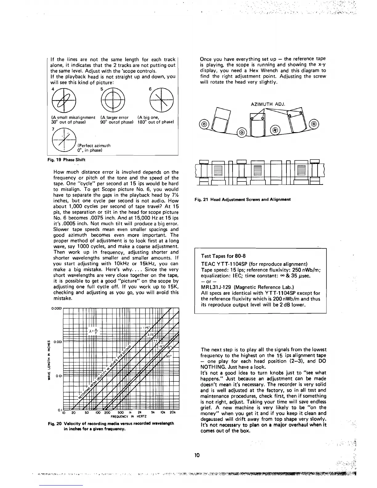
How much distance error
is
involved depends on the
frequency or pitch of the tone and the speed of the
tape. One "cycle" per second at 15 ips would be hard
to misalign. To get Scope picture No.
6,
you would
have t0 separate the gaps in the playback head by 7%
inches, but one cycle per second
is
not audio. How
about 1,000 cycles per second of tape travel? At 15
pis, the separation or tilt in the head for scope picture
No.
6
becomes .O075 inch. And at 1 5,000 Hz
at
15 ips
it's
.O005 inch. Not much tilt will produce
a
big error.
Slower tape speeds mean even smaller
spacings and
good azimuth becomes even more important. The
proper method of adjustment
is
to look first
at
a long
wave, say 1000 cycles, and make a coarse adjustment.
Then work up in frequency, adjusting shorter and
shorter wavelengths smaller and smaller amounts.
If
you start adjusting with 10kHz or 15kHz, you can
make a big mistake. Here's why.
. .
.
Since the very
short wavelengths are very
close together on the tape,
it is possible to get a good "picture" on the scope by
adjusting one
full cycle off. If you work up to 15K.
checking and adjusting as you go, you will avoid this
mista ke.
0.OWi
y
0.001
I
O
z
z
x
s
W
r
001
1
o
l
IO
20
50
100
200
500 li 21 5k Ok 20k
FREQUENCY
IN
HERTZ
Fig. 20 Velocity of recording media versus recorded wavelength
in inches for e given frequency.
Once you have everything
set
up
-
the reference tape
is
playing, the scope
is
running and showing the X-y
display, you need a Hex Wrench and this diagram to
find the right adjustment point. Adjusting the screw
will rotate the head very
slightly.
AZIMUTH
ADJ.
Fig. 21 Head Adjustment Screws and Alignment
Test Tapes for
80-8
TEAC YTT-1104SP (for reproduce alignment)
Tape speed: 15 ips; reference fluxivity: 250
nWb/m;
equalization: IEC; time constant:
&
35 psec.
-
or
-
M R L31 J-129 (Magnetic Reference Lab.)
All specs are identica1 with YTT-1104SP except for
the reference fluxivity which
is
200 nWb/m and thus
its reproduce output level will be 2
dB lower.
The next step
is to play al1 the signals from the lowest
frequency to the highest on the
15 ips alignment tape
-
one play for each head position (2-3). and DO
NOTH ING. Just
have a look.
It's
not a good idea to turn knobs just to "see what
happens." Just because an adjustment
can
be
made
doesn't mean
it's
necessary. The recorder
is
very solid
and
is
well adjusted at the factory, so in al1 test and
maintenance procedures, check first, then if something
is
not right, adjust. Taking your time will save endless
grief. A new
machine
is
very likely to be "on the
money" when you get
it
and if you keep
it
clean and
degaussed will
drift away from top shape very slowly.
It's not necessary to plan on a major overhaul when
it
comes out of the box.