Now you can use the MONITOR head
as
a
test
instrument to check and adjust the record circuits.
Almost
al1 of the following steps involve recording
a
tone on
a
tape and reading the playback output of the
recorder. YOU WON'T ALTER THE PLAYBACK
CONTROLS. They are now
al1
set. You will make al1
necessary adjustments by trimming the record electron-
ICS.
This way, you can be sure that the recordings you
make, no matter what brand of tape you use
(the
brand of tape becomes part of the test procedure when
you record your test tones on
it),
will playback
properl y on any 80-8.
The alignment tape
can be put away. Before storing,
the tape should be played
al1 the way from front to
back (not fast wound), and stored
tails out, so it will
last
longer. Even if you decide not to attempt any
major maintenance yourself, we strongly suggest you
purchase an alignment tape. An
occasiona1 playing will
tell you when you
need to call the"doctor".
It's
good
insurance to know the truth.
The record adjustments
begin with the INPUT MONIT
LEVEL trim of the 80-8.
The INPUT MONIT LEVEL
controls the meter reading of the signal
as
it
arrives
at
the electronics (before
it
is
recorded). You must be
sure you are sending the right amount of signal in
before you
can adjust record levels
ad
equalization
controls.
Connect the reference level, or signal generator to track
1 input on the 80-8. The correct level
is
-10 dB
(0.3 V).
The frequency to use
is
1 kHz. Rotate the front panel
knob to the
"2
o'clock" position. It's
a
good idea to
mark
it.
Check the OUTPUT SELECT. Make sure you
have the button marked INPUT depressed. If you get a
reading, use trim pot
#6
R107,
22
kOhms, INPUT
MONIT LEVEL, and adjust the meter to
read
O
VU.
As
always, repeat this check on al1 8 tracks of the 80-8.
Plugging and unplugging test equipment
can be tedious.
You
can save some time by doing
a
reference check on
your mixer.
If you know that your console meter reads
O
VU accurately (check
it
with the VTVM), you can
assign the reference oscillator signals to the 80-8
through the mixer connections to the inputs. Assign,
read, adjust: next track, assign, read adjust.
.
.
no need
t0
pull plugs.
ABOUT THE BIAS:
At this point in the adjustment procedure we'll stop
for
a
time and talk about
a
major section of the
recorder electronics. The Bias Oscillator and
its
related
circuitry. The Bias Oscillator produces
a
very high
frequency signal that does two big jobs in the80-8.
It
supplies the 100 kHz (one hundred thousand cycles per
second) frequency to the Bias Amplifiers in the 80-8.
There is a Bias Amplifier on every card, one for each
track. The Bias Amplifier provides power for the
erase
head and bias signal for the record head. Erasure
is
easy
to explain, so we'll tackle that subject first. A lot of
power
is
used to remove al1 signal from the tape just
prior to
its
being recorded. The erase head has
a
rather
large gap and completely cleans off any magnetic field
on the tape
by
brute force. No new signal
is
recorded
by this head. The gap
is
much too large to be effective
as
a
recording device.
From the same amplifier, current
is
added to the
record head circuit
lead. This high frequency signal
overcomes magnetic inertia in tape, and gets everything
moving.
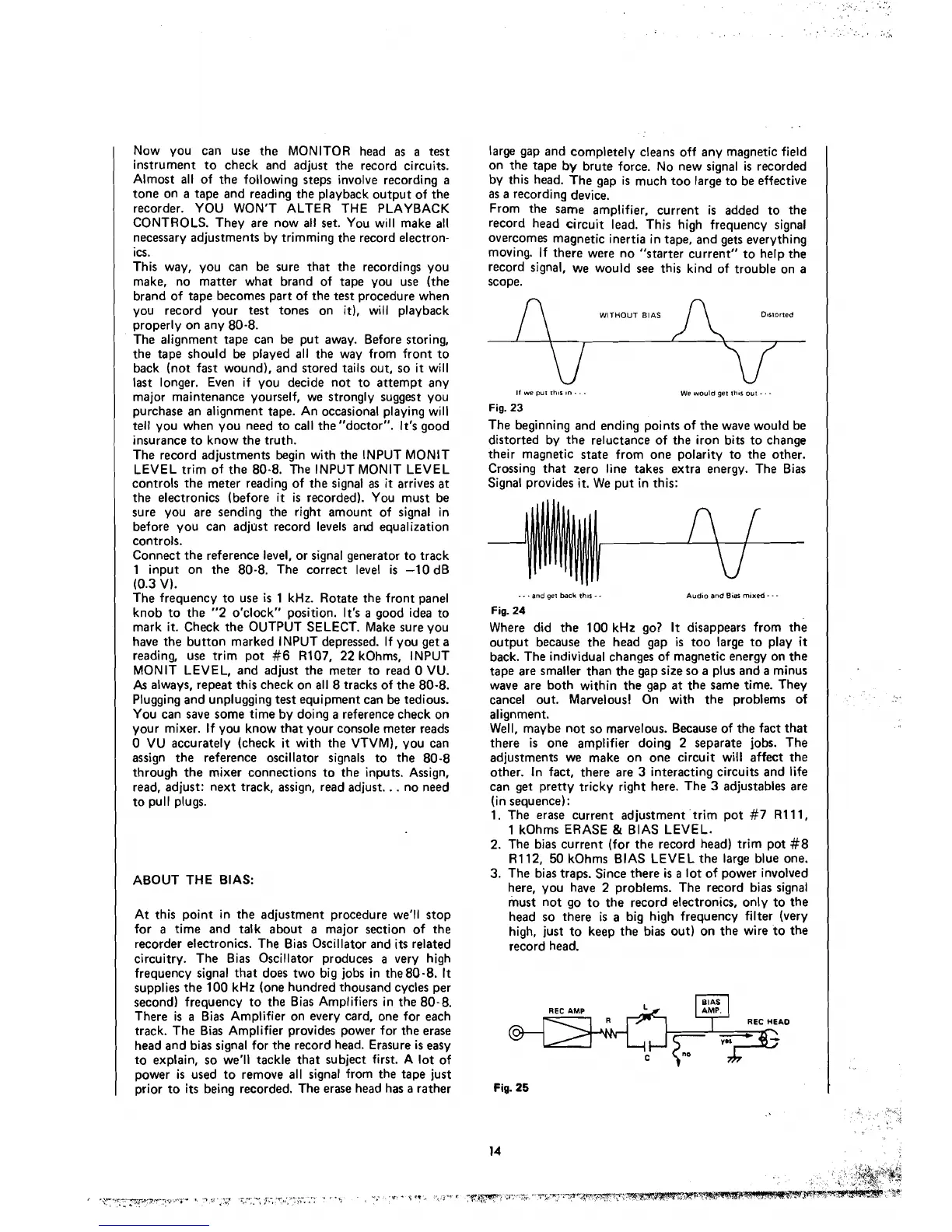
If there were no "starter current" to help the
record signal, we would see this kind of trouble on a
scope.
WITHOUT
BIAS D~rrorted
If
we
pul rh~s
in.
-
.
Fig.
23
We
would get ihir oui
The beginning and ending points of the wave would be
distorted by the reluctance of the iron bits to change
their magnetic state from one polarity to the other.
Crossing that zero Iine takes extra energy. The Bias
Signal provides
it.
We put in this:
- -
.
and
gei
back
thir
-
.
Audio and
Bis
rnixed
- - -
Fig.
24
Where did the 100 kHz go?
It
disappears from the
output because the head gap
is
too large to play
it
back. The individua1 changes of magnetic energy on the
tape are
smaller than the gap size so a plus and a minus
wave are both within the gap
at
the same time. They
cancel out.
Mawelous! On with the problems of
alignment.
Well, maybe not so marvelous. Because of the fact that
there
is
one amplifier doing
2
separate jobs. The
adjustments we make on one circuit
wili affect the
other. In fact, there are 3 interacting circuits and life
can get pretty tricky right here. The 3 adjustables are
(in sequence):
1. The
erase current adjustment trim pot #7 R111,
1 k0hms ERASE
&
BIAS LEVEL.
2.
The bias current (for the record head) trim pot #8
R112, 50 kOhms BIAS LEVEL the large blue one.
3. The bias traps.
Since there
is
a
lot of power involved
here, you
have
2
problems. The record bias signal
must not go to the record electronics, only to the
head so there
is
a big high frequency filter (very
high, just
to keep the bias out) on the wire to the
record head.
I
BIAS
I
I
7
REC
HEAO
I
REC
AMP
l
Fig.
25
t