Note: Value of "dB"in the Data refers to OdB
=
lV, ex-
For example, -10 dB (0.3V)
is
applied to the line in
cept where specified.
If
a
Test Set or VTVM calibrated
jacks, the VTVM which
is
connected
at
the line out
to
O
dB
=
0.775V
is
to be used, appropriate compensa- put jacks reads -7.8dB (0.3V) instead of -10dB
tion should be made. (0.3V).
I
I
I
Electrical Adjustment Procedure
I
REPRODUCE CALIBRATION:
When we're
sure the playback and record heads are
properly aligned, we
can move on to the electronic
adjustments.
The first step here
is
to actually check your merer caii-
bration. To open the service door loosen the 2 captive
screws, one in each upper corner. The panel hinge re-
quires
a
clearance of about 318" before it can
tilt
forward, so
a
sliding mount on the bottom edge of the
service door has been provided. Draw the entire panel
straight out slightly before attempting to tilt the top
edge forward.
Connect the VTVM to the output
termina1 of track 1.
Turn the
machine ON, and thread the 15 ips alignment
tape. Play the "operating level" portion (a
voice on the
tape identifies each section
at
the beginning).
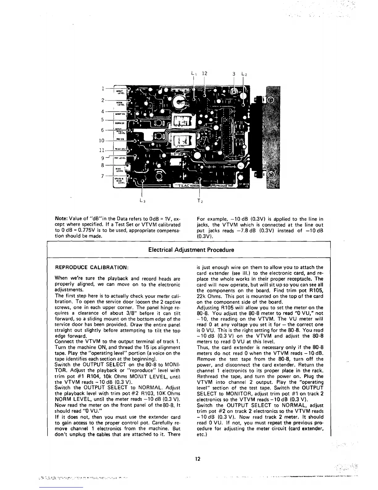
Switch the OUTPUT SELECT on the 80-8 to MONI-
TOR. Adjust the playback or "reproduce" level with
trim pot
#l
R104, 10k Ohms MONIT LEVEL, until
the VTVM reads
-
10 dB (0.3 V).
Switch the OUTPUT SELECT to NORMAL. Adjust
the playback level with trim pot
#2 R103, 10K Ohms
NORM LEVEL, until the meter reads -1 0
dB (0.3 V).
Now read the meter on the front panel of the80-8.
It
should read
"O
VU."
If
it
does not, then you must use the extender card
to gain access to the
proper contro1 pot. Carefully re-
move channel 1 electronics from the machine. But
don't unplug the cables that are attached to it. There
is just enough wire on them to allow you to attach the
card
extender (see ill.) to the electronic card, and re-
place the whole works in their proper receptacle. The
card will now operate, but will
sit
up so you can see
al1
the components on the board. Find trim pot R105,
22k Ohms. This pot is mounted on the top of the card
on the component side of the board.
Adjusting R105
will allow you to set the meter on the
80-8. You adjust the 80-8 meter to
read
"O
VU," not
-10, the reading on the VTVM. The VU meter will
read
O
at
any voltage you set
it
for
-
the correct one
is
O
VU. This is the right setting for the 80-8. You read
-10 dB (0.3 V) on the VTVM and adjust the 80-8
meters to
read
O
VU
at
this level.
Thus, the card
extender is necessary only if the 80-8
meters do not
read
O
when the VTVM reads -10 dB.
Remove the test tape from the 80-8, turn off the
power, and disconnect the card extender. Return the
channel 1 electronics to
its
proper place in the rack.
Rethread the tape, and turn the power on. Plug the
VTVM into channel 2 output. Play the "operating
level" section of the
test
tape. Switch the OUTPUT
SELECT to MONITOR, adjust trim pot
#l
on track 2
electronics so the VTVM reads -10
dB (0.3 V).
Switch the OUTPUT SELECT to NORMAL, adjust
trim pot
#2 on track 2 electronics so the VTVM reads
-
10 dB (0.3 V). Now read track 2 meter. It should
read
O
VU. If not, you must repeat the previous pro-
cedure for adjusting the meter circuit (card extender,
etc.)