THEORY OF OPERATION-MAI NTENANCE(contlnued)
Electrical
Adjustrnent Procedure
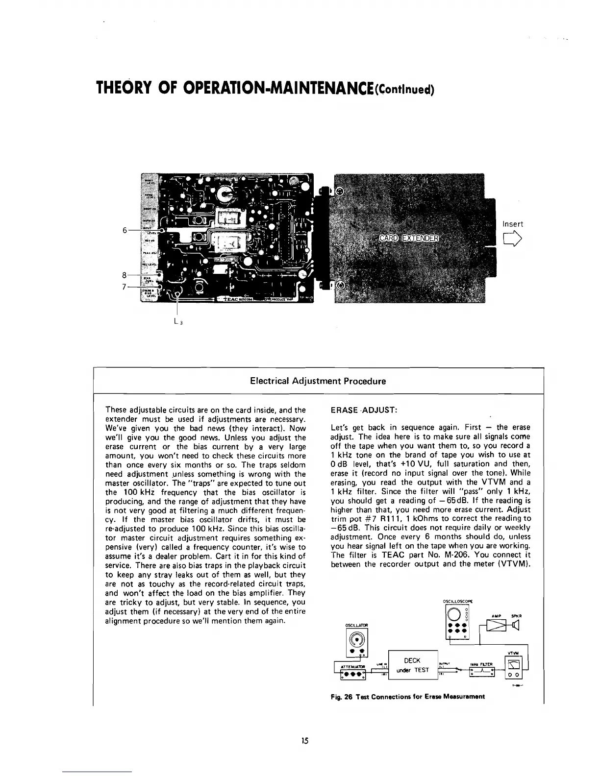
These adjustable circuits are on the card inside, and the
ERASE .ADJUST:
extender must be used if adjustments are necessary.
We've given you the bad news (they interact). Now
Let's get back in sequence again.
First
-
the erase
we'll give you the good news. Unless you adjust the
adjust. The idea here is to make sure al1 signals come
erase current or the bias current by a very large
off the tape when you want them to, so you record a
amount, you won't
need to check these circuits more
1
kHz tone on the brand of tape you wish to use at
than once every six months or so. The traps seldom
O
dB level, that's +l0 VU, full saturation and then,
need adjustment .unless something is wrong with the
erase
it
(record no input signal over the tone). While
master oscillator. The "traps" are expected to tune out
erasing, you read the output with the VTVM and a
the 100
kHi frequency that the bias oscillator is 1 kHz filter. Since the filter will "pass" only 1 kHz,
producing, and the range of adjustment that they have you should get a reading of -65dB. If the reading
is
is not very good at filtering a much different frequen- higher than that, you need more erase current. Adjust
cy. If the master bias oscillator drifts, it must be trim pot
#7
R111, 1 kOhms to correct the reading to
re-adjusted to produce 100
kHz. Since this bias oscilla- -65 dB. This circuit does not require daily or weekly
tor master circuit adjustment
requires something ex-
adjustment. Once every 6 months
should do, unless
pensive (very) called a frequency counter, it's wise to you hear signal left on the tape when you are working.
assume
it's
a dealer problem. Cart it in for this kind of The filter
is
TEAC part No. M-206. You connect it
service. There are also bias traps in the playback circuit between the recorder output and the meter (vTvM).
to keep any stray leaks out of them as well, but they
are not as touchy as the
record-related circuit traps,
and won't affect the load on the bias amplifier. They
are tricky to adjust, but very stable.
In
sequence, you
OSCI~~OSCOPE
adjust them (if necessary) at the very end of the entire
A~~
SMR
alignment procedure so we'll mention them again.
OX~LLP~W
O
DECK
under
TEST
..-.m
Fig.
26
Test
Connections for Erese Measurament
VTW
,,,
imi
FLTER
a
.--o
a-
0 0